BE1-BPR Calibration And Testing
8-3
Note
Steps 3 through 16 of this procedure can be automated by using any word processor to
type all the required commands into an ASCII file. This file would then be downloaded to
the relay using any standard communications software package or by printing the file to
the serial port. This procedure requires that the communications program or the computer
serial port communication mode supports handshaking (flow control).
CHANGES SAVED
RELAY ON-LINE
>
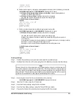
B. Define custom logic by changing a preprogrammed scheme with the following commands:
>ACCESS=<password> or ACCESS=BPR if password not used.
> LN=<name of preprogrammed scheme to modify> (copies preprogrammed
scheme to custom logic memory)
> LN=<name of new scheme> (allows scheme to be changed)
Use LO, LF, LC, LT commands as required to change logic.
>LOGIC=<name of new scheme>
>SAVE
ARE YOU SURE (Y/N)?
- Y
RELAY OFF-LINE
CHANGES
SAVED
RELAY
ON-LINE
>
C. Define a custom logic scheme without copying any previous file.
>ACCESS=<password> or ACCESS=BPR if password not used.
> LN=<name of new scheme> (allows scheme to be changed)
Use LO, LF, LC, LT commands as required to change logic.
Disable the outputs or function modules not needed by setting them equal to 0.
(I.E. LO12=0)
All equations in a group can be programmed or disabled at once by not using a number.
Example 1: LC=2,12 changes all input logic to 2,12.
Example 2: LO=0 clears all output equations before writing new ones.
>LOGIC=<name of new scheme>
>SAVE
ARE YOU SURE (Y/N)?
- Y
RELAY OFF-LINE
CHANGES SAVED
RELAY ON-LINE
>
Entering Settings
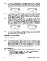
Step 1.
Perform the preliminary setup procedure and select the operational logic.
Step 2.
Calibrate the A/D section of the relay using the A/D calibration procedure described above.
Step 3.
Enter program mode from the communication port by entering :
>ACCESS=<password> or ACCESS=BPR if password not used.
Step 4.
Enter the CT ratios, using the CT command.
Step 5.
Enter the PickUp settings, using the PU command.
Step 6.
Enter the Time Delay settings, using the TD and TD79 commands.
Step 7.
Program the format of the real-time-clock by using the PCLK command.
Summary of Contents for BE1-BPR
Page 31: ...BE1 BPR Application 2 17...
Page 42: ...3 4 BE1 BPR Human Machine Interface Figure 3 4 BE1 BPR Relay Vertical Mount Front View...
Page 43: ...BE1 BPR Human Machine Interface 3 5 Figure 3 5 BE1 BPR Relay Vertical Mount Rear View...
Page 49: ...4 6 BE1 BPR Functional Description Figure 4 2 Enhanced BE1 BPR Menu Display Screens...
Page 50: ...BE1 BPR Functional Description 4 7 Figure 4 3 Standard BE1 BPR Menu Display Screens...
Page 94: ...5 4 BE1 BPR BESTlogic Figure 5 1 BESTlogic Function Blocks...
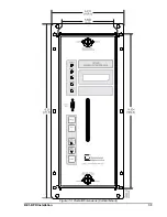
Page 121: ...BE1 BPR Installation 7 3 Figure 7 3 Overall Dimensions Vertical Mount...
Page 122: ...7 4 BE1 BPR Installation Figure 7 4 Overall Dimensions Side View Vertical Mount...
Page 123: ...BE1 BPR Installation 7 5 Figure 7 5 Panel Drilling Diagram Vertical Mount...

