4-22
BE1-BPR Functional Description
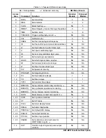
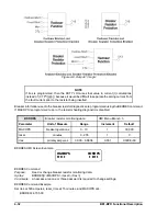
NOTE
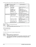
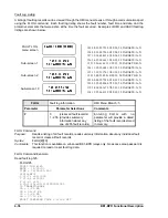
After the programmable logic is changed or the time delay settings are changed, the
recloser initializes as described in the
Reclosing Mode, TYPE 1 or TYPE 2.
DTL:
Drives the reclose function immediately to the lockout state. Lockout has precedence over all
other inputs. When lockout is removed and the breaker is closed, the recloser begins reset
timing. When lockout is removed and the breaker is open, the recloser remains in the lockout
state.
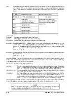
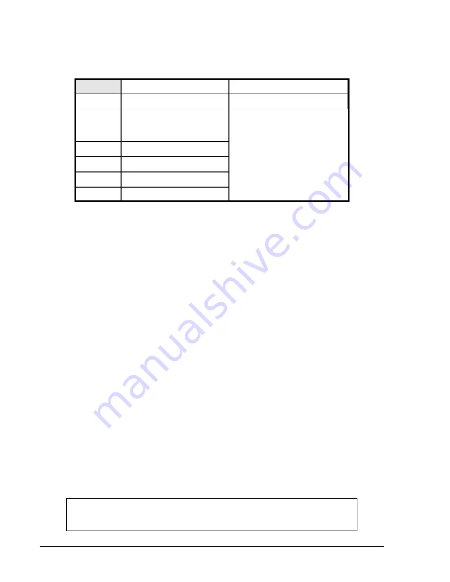
LR
Recloser input logic
HMI Menu Branch: N/A
Parameter
Parameter Selections
Comments
type
0 (disabled)
1 (standard recloser)
2 (power-up to reclose)
The recloser is enabled only
when the type selection is 1 or 2
and the start and reset logic is
programmed.
start
any logic variable
reset
any logic variable
wait
any logic variable
lockout
any logic variable
LR Command
Purpose:
Reads or programs the recloser input logic.
Syntax:
LR [=<type>,<start>,<reset>,<wait>,<lockout>]
Comments:
Access area one password is required to change setting.
Example 1: Define a recloser that is initiated by any TRUE signal to the breaker and reset when the 52a
contact closes. Given: Previous BESTlogic definitions have defined a logic scheme that has
all BFI TRIP signals driving O5 for a retrip function, and have defined I1 to be a 52a input, I6 to
be a wait input, and I7 to be a drive to lockout input.
LR=1, O5, I1, I6, I7
Example 2: Define the same logic except that a 52b input is connected to I1 instead of the 52a and there
is no wait input.
LR=1, O5, /I1, 0, I7
Recloser Outputs. There is a CLOSE output on O13 and diagnostic status flags for reclose fail and lockout.
Output O13 and the diagnostics for reclose fail and lockout can be programmed to drive output relay
contacts by using the LO and PDIAG commands.
The function of each output or flag is defined as:
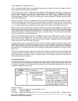
CLOSE:
The reclose output contacts close at the end of each reclose time delay. They open
when the RESET input shows that the breaker has closed, when the reclose fail timer
times out, or when the recloser goes to LOCKOUT or the WAIT input is asserted.
RECLOSE FAIL:
The reclose fail diagnostic flag is set when the reclose fail timer times out and remains
set until the recloser goes to the reset state.
LOCKOUT:
The lockout flag is set when the recloser goes to LOCKOUT and remains set until the
recloser goes to the reset state. The recloser goes to LOCKOUT if more than the maxi-
mum number of shots programmed is initiated before the recloser returns to the reset
state, if the Drive to Lockout (DTL) input is TRUE, or if RECLOSE FAIL is TRUE.
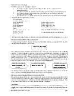
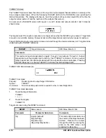
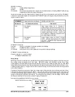
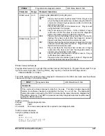
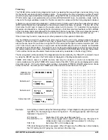
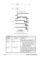
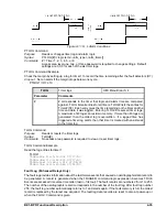
Reclosing Mode (TYPE). Reclosing mode controls the reclosing sequence on power-up. There are three
modes of operation and one is selected by setting the TYPE in the LR command to 0, 1, or 2.
Summary of Contents for BE1-BPR
Page 31: ...BE1 BPR Application 2 17...
Page 42: ...3 4 BE1 BPR Human Machine Interface Figure 3 4 BE1 BPR Relay Vertical Mount Front View...
Page 43: ...BE1 BPR Human Machine Interface 3 5 Figure 3 5 BE1 BPR Relay Vertical Mount Rear View...
Page 49: ...4 6 BE1 BPR Functional Description Figure 4 2 Enhanced BE1 BPR Menu Display Screens...
Page 50: ...BE1 BPR Functional Description 4 7 Figure 4 3 Standard BE1 BPR Menu Display Screens...
Page 94: ...5 4 BE1 BPR BESTlogic Figure 5 1 BESTlogic Function Blocks...
Page 121: ...BE1 BPR Installation 7 3 Figure 7 3 Overall Dimensions Vertical Mount...
Page 122: ...7 4 BE1 BPR Installation Figure 7 4 Overall Dimensions Side View Vertical Mount...
Page 123: ...BE1 BPR Installation 7 5 Figure 7 5 Panel Drilling Diagram Vertical Mount...

