5-6
BE1-BPR BESTlogic
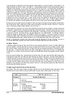
Logic equations are defined by the logic variables, logical operators, and their position in the equation. The
logical operators are AND (*), OR (+), and NOT (/). Logical operator AND (*) is assumed between adjacent
variables or parentheses; i.e., (F1+F2)I1O1 is the same as (F1+F2)*I1*O1. The logical NOT operator (/) is
applied to the variable immediately following the symbol /. A logical NOT operator may be applied to a single
variable or to a group enclosed in parentheses. When NOT is used with parenthesis, the number of
operators is limited to four. Internally, the logic equations defined are reduced to a
canonical sum-of-products
form; i.e., groups of ANDed terms separated by ORs with parenthesis eliminated. When the logic equation
is read back, the internal format is given. The number of terms when expanded to a canonical sum-of
products form must not exceed four. In other words, when the equation is expanded by removing all
parentheses, the number of OR symbols in the equation must be three or less. If a larger number of terms
are needed, this limitation may be bypassed by using a virtual output as an intermediate expression.
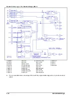
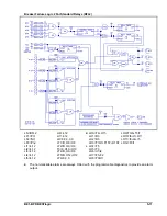
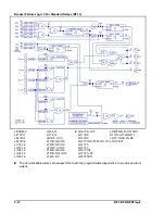
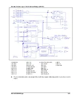
During power-up, all logic outputs are disabled. When the logic is running and logic equation LO[n] is false,
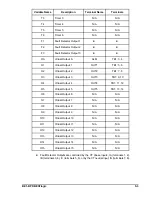
then Output O[n] = false, where O[n] corresponds to terminals for OUT[n] as shown in Table 5-1. When the
logic is running and logic equation LO[n] is true, then O[n] = 1.
Virtual Outputs 13 through 15 (O13-O15) are dedicated outputs that are controlled by a function instead of
an equation. Output O13 is controlled by the Recloser (79) function block. If the Recloser function isn’t used,
O13 is controlled by the Breaker Resistor Protection Module. The Recloser function is defined when the LR
command is entered. The logic scheme will then display O13 as a RECLOSER. The Breaker Resistor
Protection Module is defined when the BKRRES command is entered. The logic equation for O13 is
displayed as ROP_LIMIT if the Recloser function is not used and BKRRES is defined. Outputs O14 and O15
are programmable diagnostic outputs that allow one or more diagnostic alarms to be annunciated.
Section 2,
Applications provides more information about the application of these functions. Section 4,
Functional Description provides information about the settings associated with these functions.
Hardware Outputs
A hardware output is a physical relay contact that can be used for protection or control. The BE1-BPR relay
has five isolated, normally open (N.O.) output contacts (OUT1-OUT5) and one isolated normally closed
(N.C.) alarm output. Output contacts OUT1 through OUT5 are controlled by the status of virtual outputs VO1
through VO5. If VO[n] becomes TRUE, then the corresponding output relay (OUT[n]) is energized and
closes the N.O. contacts. If VOA becomes TRUE, the ALARM output relay de-energizes and the contacts
close.
When an output changes state, internal logic can hold the relay in the new state for 200 to 250 milliseconds.
Following this holdup time, the output resumes following the internal VO[n] logic. The 200 to 250 millisecond
minimum ON time is used to ensure that once a trip contact closes, it doesn’t interrupt the breaker trip coil
current, but does allow the trip coil current to be interrupted by the 52A contact. In some instances, such as
a recloser module breaker close contact, the output hold logic may not be desired. The hold logic can be
disabled on any contact by the PHOLD command. Section 4,
Functional Description provides information
about using the PHOLD command.
Programming Output Operational Characteristics
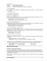
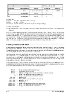
Each output, O[n], has a logical mode of operation defined in terms of a standard boolean expression, LO[n].
Variables can be any contact input (I[n]), fault detector output (F[n]), output (O[n]), or timer (T[n]).
LO
Output logic
HMI Menu Branch: N/A
Parameter
Parameter Selections
#
A (OUTA)
1-15 (OUT1-OUT15)
Boolean
Equation
Variables:
Operators:
Ix (contact inputs)
* (AND)
Fx (fault detector outputs)
+ (OR)
Tx (timer outputs)
/ (NOT)
Ox (virtual outputs)
Summary of Contents for BE1-BPR
Page 31: ...BE1 BPR Application 2 17...
Page 42: ...3 4 BE1 BPR Human Machine Interface Figure 3 4 BE1 BPR Relay Vertical Mount Front View...
Page 43: ...BE1 BPR Human Machine Interface 3 5 Figure 3 5 BE1 BPR Relay Vertical Mount Rear View...
Page 49: ...4 6 BE1 BPR Functional Description Figure 4 2 Enhanced BE1 BPR Menu Display Screens...
Page 50: ...BE1 BPR Functional Description 4 7 Figure 4 3 Standard BE1 BPR Menu Display Screens...
Page 94: ...5 4 BE1 BPR BESTlogic Figure 5 1 BESTlogic Function Blocks...
Page 121: ...BE1 BPR Installation 7 3 Figure 7 3 Overall Dimensions Vertical Mount...
Page 122: ...7 4 BE1 BPR Installation Figure 7 4 Overall Dimensions Side View Vertical Mount...
Page 123: ...BE1 BPR Installation 7 5 Figure 7 5 Panel Drilling Diagram Vertical Mount...


