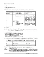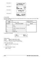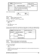
BE1-BPR Functional Description
4-27
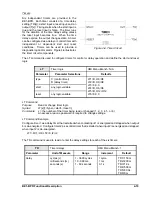
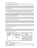
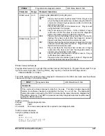
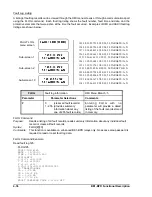
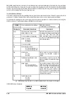
PDIAG
Programmable diagnostic alarms
HMI Menu Branch: N/A
Parameter
Range
Parameter Selections
DIAG1 mask
0 or 1
<(OA)(TL)(DL)(BKR)(RST)(CLK)(RF)(LO)>
where:
OA
Flag is set when LOA logic becomes TRUE. Flag is reset
when the diagnostic alarms are cleared using the DIAG=0
command. Allows a logic expression written to LOA to be
latched and reported.
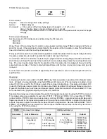
TL
Flag is set when any TLOG alarms occur. Flag is reset
using the DIAG=0 command.
DL
Flag is set when any DLOG is
100% of DMAX. Flag is
reset when the DLOG value is reset and the diagnostic
alarms are cleared using the DIAG=0 command.
BKR
Flag is set when the breaker takes more than 1 second to
interrupt the phase current after the breaker is opened.
Flag is reset when the DIAG=0 command is used.
RST
Flag is set when the microprocessor is reset due to a loss
of power or watchdog timer operation. Flag is reset when
the DIAG=0 command is used.
CLK
Flag is set when the time clock has not been set. Flag is
reset when the clock is set and the diagnostic alarm is
cleared using the DIAG=0 command.
RF
Flag is set when the Reclose Fail Alarm occurs. Flag is
reset when the breaker closes.
LO
Flag is set when the recloser goes to lockout. Flag is reset
when the recloser comes out of lockout.
DIAG2 mask
0 or 1
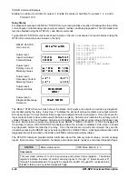
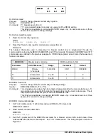
PDIAG Command Example
Program virtual output 14 to go high if the recloser lockout (LO) flag is set. Program virtual output 15 to go
high if the alarm logic (OA), timer log (TLOG), duty log (DL), or reclose fail (RF) flags are set.
PDIAG=00000001,11100010
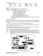
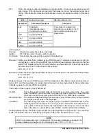
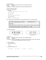
The TEST command provides the same diagnostic information as the DIAG command plus the software
checksum and relay on-line/off-line status.
TEST
Diagnostic data
HMI Menu Branch: N/A
Comments
This command retrieves diagnostic data from the relay. This data includes diagnostic
alarms, the software checksum, and whether the relay is on or off line. The diagnostic
alarm information retrieved by the TEST command is the same information displayed by
the DIAG command. The TEST command is read only; diagnostic alarms should be reset
using the DIAG command.
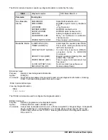
TEST Command
Purpose:
Reads diagnostic data.
Syntax:
TEST
Comments:
No access area password is required to read diagnostic data.
TEST Command Example
Verify the software checksum.
TEST
RELAY ON-LINE
DIAG: 1 OF 2 CLOCK NOT SET
PROGRAM CHECKSUM: 3C7E
Summary of Contents for BE1-BPR
Page 31: ...BE1 BPR Application 2 17...
Page 42: ...3 4 BE1 BPR Human Machine Interface Figure 3 4 BE1 BPR Relay Vertical Mount Front View...
Page 43: ...BE1 BPR Human Machine Interface 3 5 Figure 3 5 BE1 BPR Relay Vertical Mount Rear View...
Page 49: ...4 6 BE1 BPR Functional Description Figure 4 2 Enhanced BE1 BPR Menu Display Screens...
Page 50: ...BE1 BPR Functional Description 4 7 Figure 4 3 Standard BE1 BPR Menu Display Screens...
Page 94: ...5 4 BE1 BPR BESTlogic Figure 5 1 BESTlogic Function Blocks...
Page 121: ...BE1 BPR Installation 7 3 Figure 7 3 Overall Dimensions Vertical Mount...
Page 122: ...7 4 BE1 BPR Installation Figure 7 4 Overall Dimensions Side View Vertical Mount...
Page 123: ...BE1 BPR Installation 7 5 Figure 7 5 Panel Drilling Diagram Vertical Mount...

