4-20
BE1-BPR Functional Description
7'
7'
7'
P
P
V
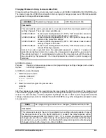
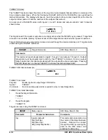
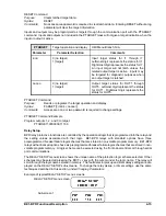
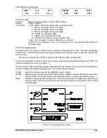
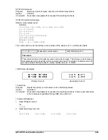
TD HMI Screen Example
TD Command
Purpose:
Read or change timer delay settings
Syntax:
TD[x][=<delay>]]
Comments:
x = the number of the timer being read or changed (1, 2, 3, 4, 5, or 6)
delay = the time delay in cycles, milliseconds, or seconds
A setting of zero disables a timer. An access area one or two password is required to change
settings.
TD Command Examples
Set time delay 2 at 100 milliseconds and time delay 5 at 30 seconds.
TD2=100
TD5=30S
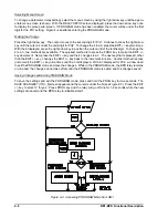
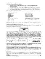
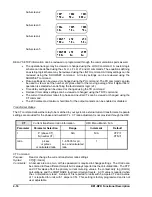
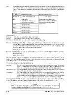
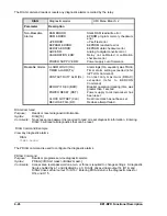
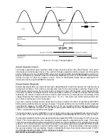
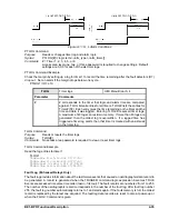
Delay Timer. When a delay timer is started, a pre-programmed time delay (TD[x]) is loaded and the timer
starts timing out. If the reset input remains false for the duration of the time delay, output T[x] will become
true and remain true until the reset input becomes true.
This type of timer is useful in a breaker failure application where the breaker failure output is delayed to allow
the primary protection elements to operate the breaker and open the circuit.
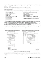
Control Timer. When a control timer is started, a pre-programmed time delay (TD[x]) is loaded and the timer
starts timing out. Output T[x] is true for the duration of the time delay setting unless the reset input becomes
true. If the reset input remains false for the duration of the time delay, the time delay will time out and the
output will become false. The timer output will remain false until the timer is reset and a new start input is
received.
A control timer can provide a window of opportunity for an operation to occur or ensure input latch-in for a
specified time.
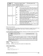
Reclosing
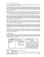
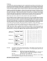
A Reclosing Function is provided in the BE1-BPR relay that can operate in parallel with the breaker failure
logic. All inputs are programmable using the BESTlogic LR command. When reclosing is enabled, virtual
output 13 (O13) is used for the 79 Close output of the recloser function block. If reclosing is disabled, O13
is used for the breaker resistor protection function output that is described in the
Breaker Status sub-section.
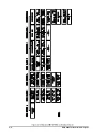
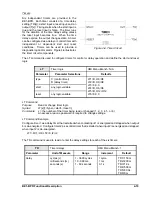
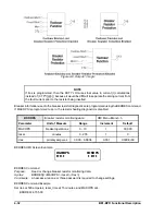
Figure 4-8 illustrates how the recloser and breaker resistor protection function if both are enabled. O13 can
be connected to any physical output by using the LO command.
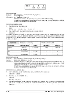
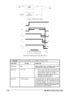
Separate time delays are programmable through the front panel or serial port by using the TD79 command.
Time delay settings are available for each shot (TD791, TD792 and TD793), for the reset timer (TD79R),
reclose fail timer (TD79F) and a maximum reclose cycle timer (TD79M). Lockout and reclose fail diagnostic
flags are set/reset by the recloser diagnostics and by using the command PDIAG to program the diagnostic
outputs. Separate outputs for lockout and reclose fail can be programmed. Reclosed state (RESET, WAIT,
TIMING, or LOCKOUT) can be viewed from the front panel recloser status screen in the relay status menu
or by using the STATUS command.
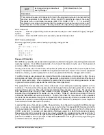
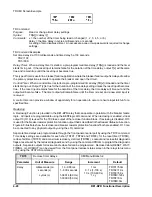
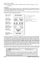
TD79
Reclose timer delays
HMI Menu Branch: 2
Parameter
Unit of Measure
Range
Increment
Default
delay
milliseconds (m)
seconds (s)
cycles (c)
10 - 999 ms
1 - 600 seconds
1-36014 (60 Hz)
1-30000 (50 Hz)
1 ms
0.1 s (1-100 s)
1.0 s (100-600 s)
1 cy
TD791=50m
TD792=1.0s
TD793=5.0s
TD79R=120s
TD79F=0m
TD79M=0m
Summary of Contents for BE1-BPR
Page 31: ...BE1 BPR Application 2 17...
Page 42: ...3 4 BE1 BPR Human Machine Interface Figure 3 4 BE1 BPR Relay Vertical Mount Front View...
Page 43: ...BE1 BPR Human Machine Interface 3 5 Figure 3 5 BE1 BPR Relay Vertical Mount Rear View...
Page 49: ...4 6 BE1 BPR Functional Description Figure 4 2 Enhanced BE1 BPR Menu Display Screens...
Page 50: ...BE1 BPR Functional Description 4 7 Figure 4 3 Standard BE1 BPR Menu Display Screens...
Page 94: ...5 4 BE1 BPR BESTlogic Figure 5 1 BESTlogic Function Blocks...
Page 121: ...BE1 BPR Installation 7 3 Figure 7 3 Overall Dimensions Vertical Mount...
Page 122: ...7 4 BE1 BPR Installation Figure 7 4 Overall Dimensions Side View Vertical Mount...
Page 123: ...BE1 BPR Installation 7 5 Figure 7 5 Panel Drilling Diagram Vertical Mount...

