BE1-BPR Functional Description
4-21
7'
P
V
V
7'5
)
0
6
0
0
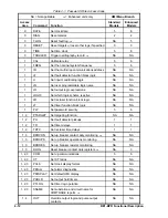
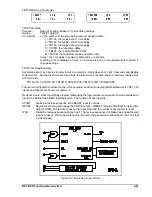
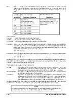
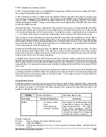
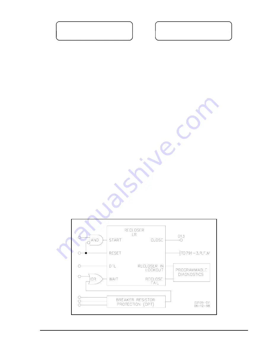
Figure 4-7. Reclosing Logic Circuit
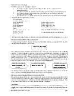
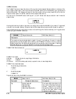
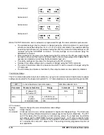
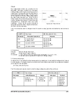
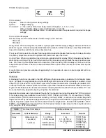
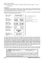
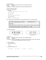
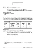
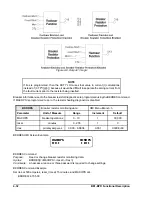
TD79 HMI Screen Examples
TD79 Command
Purpose:
Read or change recloser (79) time delay settings
Syntax:
TD[x][=<delay>]]
Comments:
x = the number of the timer being read or changed where:
1 = TD791, the reclose shot 1 time delay
2 = TD792, the reclose shot 2 time delay
3 = TD793, the reclose shot 3 time delay
R = TD79R, the reset time delay
F = TD79F, the reclose fail time delay
M = TD79M, the maximum reclose operation time
delay = the time delay in cycles, milliseconds, or seconds
A setting of zero disables a timer. An access area one or two password is required to
change settings.
TD79 Command Example
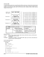
Set reclose shot 1 at 3 cycles to allow for arc de-ionization. Set reclose shot 2 at 2.5 seconds and disable
reclose shot 3. Set the reset time at 30 seconds, the fail time at 2 minutes, and the maximum reclose time
at 2.5 minutes.
TD791=3C; TD792=2.5S; TD793=0; TD79R=30S; TD79F=120S; TD79M=150S
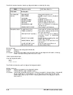
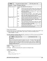
There are four inputs to a reclose function, three outputs, and one mode programmable feature (TYPE). The
inputs and outputs are shown in Figure 4-7.
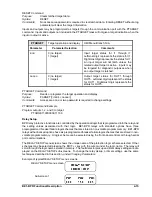
Recloser Inputs. Each input is fully programmable using the logic recloser command (LR) which allows each
input to be defined as a BESTlogic logic term. The function of each input is:
START:
Starts the reclose sequence if the RESET input is not true.
RESET:
Begins reset timing and opens the CLOSE output. If RESET remains TRUE for the reset time
delay (TD79R), the recloser goes to the reset state and the recloser shot counter is reset.
WAIT:
Stops the reclose sequence at any point. The reclose sequence is inhibited as long as the wait
input is present. When the wait input is removed, the sequence continues from the point that
it was stopped.
Summary of Contents for BE1-BPR
Page 31: ...BE1 BPR Application 2 17...
Page 42: ...3 4 BE1 BPR Human Machine Interface Figure 3 4 BE1 BPR Relay Vertical Mount Front View...
Page 43: ...BE1 BPR Human Machine Interface 3 5 Figure 3 5 BE1 BPR Relay Vertical Mount Rear View...
Page 49: ...4 6 BE1 BPR Functional Description Figure 4 2 Enhanced BE1 BPR Menu Display Screens...
Page 50: ...BE1 BPR Functional Description 4 7 Figure 4 3 Standard BE1 BPR Menu Display Screens...
Page 94: ...5 4 BE1 BPR BESTlogic Figure 5 1 BESTlogic Function Blocks...
Page 121: ...BE1 BPR Installation 7 3 Figure 7 3 Overall Dimensions Vertical Mount...
Page 122: ...7 4 BE1 BPR Installation Figure 7 4 Overall Dimensions Side View Vertical Mount...
Page 123: ...BE1 BPR Installation 7 5 Figure 7 5 Panel Drilling Diagram Vertical Mount...


