5-8
BE1-BPR BESTlogic
LI
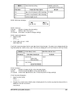
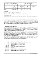
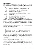
Contact input logic
HMI Menu Branch: N/A
Parameter
Unit of Measure
Range
Increment
Default
#
N/A
1, 2, 3, 4, 5, 6, or 7
N/A
LI#=4,12
r
milliseconds
4 - 255
1
db
milliseconds
4 - 255
1
LI Command
Purpose:
Reads or programs contact input logic.
Syntax:
LI [#[=<r>,<db>]]
Comments:
Access area one password is required to change settings.
LI Command Example
Configure input 3 for a contact recognition time of 10 milliseconds and a debounce time of 20 milliseconds.
LI=10,20
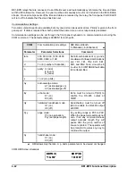
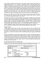
The state of the contact sensing inputs is scanned twelve times per cycle. The time settings are converted
to the nearest multiple of the scan interval which is determined by the nominal frequency setting (1.39
milliseconds at 60 hertz or 1.67 milliseconds at 50 hertz). For example, if the nominal frequency is 60 hertz,
a recognition time setting of 4 milliseconds is rounded to 4.17 milliseconds which is the nearest multiple of
the scan interval. In this case, a contact closure must be present on three consecutive scans of the input
state for it to be recognized and the BESTlogic input variable to change state from a 0 to 1.
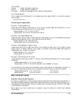
BESTlogic APPLICATION HINTS
Preprogrammed protection schemes may provide additional inputs, outputs, or features that are not needed
for all applications. This is done so that a few schemes can be used in a large number of applications with
no special programming required. The unneeded inputs or outputs may be left open to disable the function.
Unused CT inputs should be shorted to minimize noise pickup.
Additional Breaker Failure inputs have been provided in many schemes for diagnostic reasons. Target
information can be provided for inputs as well as outputs, therefore the relay that caused the breaker
operation may be identified by requesting target information through the communications port. This is
especially useful when trying to remotely determine the cause of a problem when the relay that tripped the
breaker is an older, non-communicating relay.
When designing new protection schemes, avoid unnecessary confusion by maintaining consistency wherever
possible between function of the inputs and outputs in the new scheme and the preprogrammed schemes.
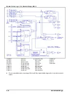
The preprogrammed schemes are consistent in the following functions:
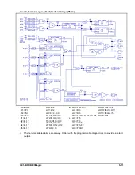
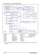
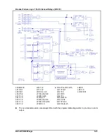
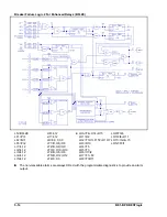
IN1 (I1)
= Breaker status contact (isolated input)
IN3 (I3)
= Primary BFI (isolated input)
IN7 (I7)
= External fault trigger to record fault records on enhanced relays
F1
= Always associated with phase fault detector
F2
= Always associated with neutral fault detector
ALM (OA)
= Alarm output
OUT1 (O1)
= Primary BFO - high speed (1/4 cycle pickup)
OUT2 (O2)
= Secondary BFO
OUT5 (O5)
= Retrip Output
TIMER1 (T1)
= Always associated with primary BFO delay timer
TIMER2 (T2)
= Always associated with alternate BFO delay timer
TIMER3 (T3)
= Always associated with the control timer
Summary of Contents for BE1-BPR
Page 31: ...BE1 BPR Application 2 17...
Page 42: ...3 4 BE1 BPR Human Machine Interface Figure 3 4 BE1 BPR Relay Vertical Mount Front View...
Page 43: ...BE1 BPR Human Machine Interface 3 5 Figure 3 5 BE1 BPR Relay Vertical Mount Rear View...
Page 49: ...4 6 BE1 BPR Functional Description Figure 4 2 Enhanced BE1 BPR Menu Display Screens...
Page 50: ...BE1 BPR Functional Description 4 7 Figure 4 3 Standard BE1 BPR Menu Display Screens...
Page 94: ...5 4 BE1 BPR BESTlogic Figure 5 1 BESTlogic Function Blocks...
Page 121: ...BE1 BPR Installation 7 3 Figure 7 3 Overall Dimensions Vertical Mount...
Page 122: ...7 4 BE1 BPR Installation Figure 7 4 Overall Dimensions Side View Vertical Mount...
Page 123: ...BE1 BPR Installation 7 5 Figure 7 5 Panel Drilling Diagram Vertical Mount...

