06.03
16.2 Expanded message frame configuration (SW 2.2 and higher)
16-502
Siemens AG, 2003. All rights reserved
SINUMERIK 840Di Manual (HBI) – 06.03 Edition
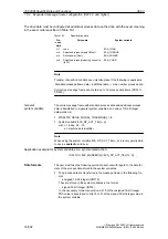
The drive data must be configured as additional process data on the drive with the exact meaning
in the exact order specified in Table 16-1.
Table 16-1
Specific drive data
Pro-
cess
data
Drive data
System variable
x+1
Load
$AA_LOAD
x+2
Smoothed torque setpoint (Mset)
$AA_TORQUE
x+3
Active power (Pact)
$AA_POWER
x+4
Smoothed torque-producing current Iq
(IqGl)
$AA_CURR
Note
Transfer of specific drive data can only take place if the following is applicable:
Standard message frame data + additional data
v
max. number process data.
Currently a message frame can contain up to 16 process data items (PDA1 to
PDA16).
The entire message frame with standard process data and additional process
data is transferred in a general system variable as an array of 16-bit integer
data words via:
S
MD 36730: DRIVE_SIGNAL_TRACKING[n] = 2
S
System variable: $VA_DP_ACT_TEL[n, a]
with n = index: 0,2,...15
a = machine axis identifier.
Note
When using the system variable $VA_DP_ACT_TEL[n, a], it is only permissible
to use a constant as index n.
Application example for system variables in a synchronized action:
IDS=1 DO $AC_MARKER[0] = $VA_DP_ACT_TEL[12, X]
The user must take the following points into account with regard to the data for-
mats of the process data stored in the system variables:
S
The process data are transferred in the message frame in the following for-
mat:
–
unsigned 16-bit integer (UINT16)
They are stored in the system variables in the format
–
signed 32-bit integer (INT32)
In the necessary format conversion, bit 15 of the unsigned 16-bit integer
PDA value is transferred to bits 16 to 31 of the signed 32-bit integer value in
the system variable.
General
system variable
Data formats
16 840Di Specific Data and Functions

