R01UH0823EJ0100 Rev.1.00
Page 1288 of 1823
Jul 31, 2019
RX23W Group
36. CAN Module (RSCAN)
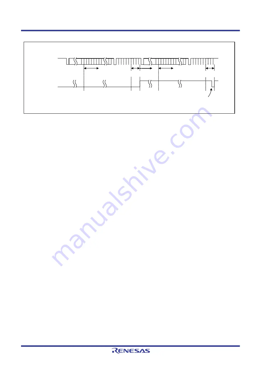
Figure 36.23
Receive Buffer Reception Timing Chart
(1) When the ID field in a message has been received, the acceptance filter processing starts.
(2) When the message matches the receive rule of the corresponding channel and the message has been successfully
received, the routing processing to transfer the message to the specified buffer starts. When the GCFGL.DCE bit is
set to 1 (DLC check is enabled), the DLC filter processing starts at this time.
(3) When the message has passed through the DLC filter processing, the processing to store the message in the
specified receive buffer starts.
When the message storage processing starts, the corresponding RMND0.RMNSn flag becomes 1 (receive buffer
contains a new message). If other channels are performing filter processing or transmit priority determination
processing, the routing processing and the storage processing may be delayed.
(4) When the ID field of the next message has been received, the acceptance filter processing starts.
(5) When the message matches the receive rule of the corresponding channel and the message has been successfully
received, the routing processing to transfer the message to the specified buffer starts. When the GCFGL.DCE bit is
set to 1 (DLC check is enabled), the DLC filter processing starts at this time.
(6) When the corresponding RMND0.RMNSn flag becomes 0 (receive buffer contains no new message), this flag
becomes 1 again when the message storage processing starts. Even if the RMND0.RMNSn flag remains 1, a new
message is overwritten to the receive buffer. The RMND0.RMNSn flag should not be set to 0 during storage of
messages.
CAN bus
RMNSn flag
(1)
(2)
(3)
(4)
SOF
Control
ID
Acceptance
filter processing
ACK
CRC
delimiter
EOF
INT
Routing and storage
processing
SOF
Control
ACK
EOF
INT
ID
Acceptance
filter processing
(5)
(6)
Routing and storage
processing
RMNSn: Flag in the RMND0 register
Cleared by the program
High
Low
1
0


