R01UH0823EJ0100 Rev.1.00
Page 218 of 1823
Jul 31, 2019
RX23W Group
10. Clock Frequency Accuracy Measurement Circuit (CAC)
10.3
Operation
10.3.1
Measuring Clock Frequency
The clock frequency accuracy measurement circuit measures the clock frequency using the CACREF pin input or the
internal clock as a reference.
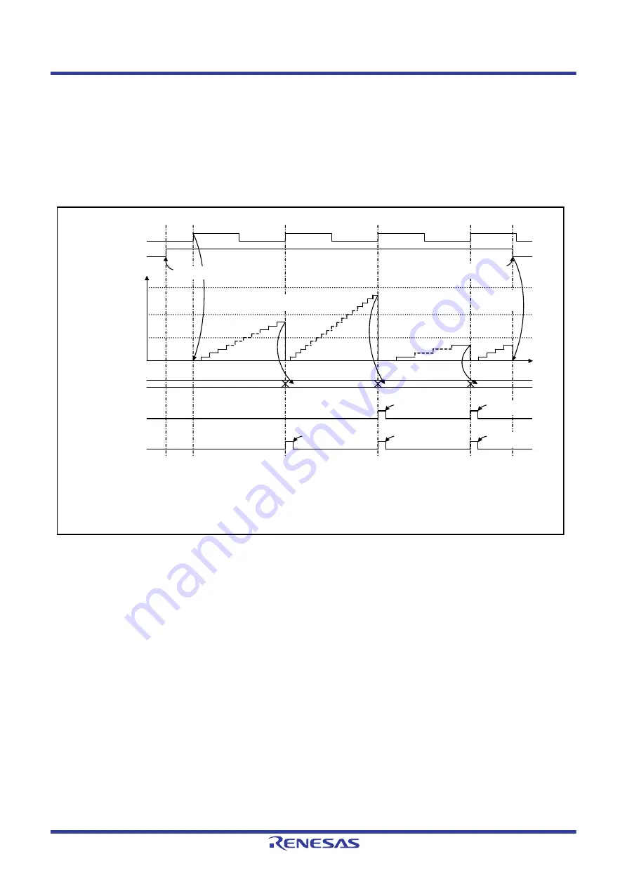
shows an operating example of the clock frequency accuracy measurement
circuit.
The clock frequency accuracy measurement circuit operates as shown below when measuring the clock frequency.
Figure 10.2
Operating Example of Clock Frequency Accuracy Measurement Circuit
(1) When the CACREF pin input is used as a reference (CACR1.CACREFE bit = 1), clock frequency measurement is
enabled by writing 1 to the CACR0.CFME bit while the CACR2.RPS bit is 0 and the CACR1.CACREFE bit is 1.
On the other hand, when the internal clock is used as a reference (CACR1.CACREFE bit = 0), clock frequency
measurement is enabled by writing 1 to the CACR0.CFME bit while the CACR2.RPS bit is 1.
(2) When the CACREF pin input is used as a reference, the timer starts up-counting if the valid edge selected by the
CACR1.EDGES[1:0] bits is input from the CACREF pin after 1 is written to the CFME bit. The valid edge is a
rising edge (CACR1.EDGES[1:0] = 00b) in
.
When the internal clock is used as a reference, the timer starts up-counting if the valid edge selected by the
CACR1.EDGES[1:0] bits is input based on the clock source selected by the CACR2.RSCS[2:0] bits after 1 is
written to the CFME bit. The valid edge is a rising edge (CACR1.EDGES[1:0] = 00b) in
(3) When the next valid edge is input, the counter value is transferred in CACNTBR and compared with the values of
CAULVR and CALLVR. If both CACNTBR ≤ CAULVR and CACNTBR ≥ CALLVR are satisfied, only the
MENDF flag in CASTR is set to 1 because the clock frequency is correct. If the MENDIE bit in CAICR is 1, a
measurement end interrupt is generated.
(4) When the next valid edge is input, the counter value is transferred in CACNTBR and compared with the values of
CAULVR and CALLVR. In the case of CACNTBR > CAULVR, the FERRF flag in CASTR is set to 1 because the
0000h
CAULVR
CALLVR
Counter value
FFFFh
Time
7FFFh
3FFFh
BFFFh
0000h
MENDF flag in CASTR
(measurement end flag)
(1)
(2)
(3)
(4)
(5)
(6)
When the CACREF pin input is used as a reference:
In CACR1: CACREFE bit = 1, EDGES[1:0] bits = 00b
CAULVR register = AAAAh, CALLVR register = 5555h
When the internal clock is used as a reference:
In CACR1: CACREFE bit = 0, EDGES[1:0] bits = 00b
CAULVR register = AAAAh, CALLVR register = 5555h
1
0
FERRF flag in CASTR
(frequency error flag)
1
0
CACNTBR
CFME bit in CACR0
1
0
CACREF pin or
internal clock
1
0
1 is written to
CFME bit.
1 is written to MENDFCL
bit in CAICR.
1 is written to MENDFCL
bit in CAICR.
1 is written to FERRFCL
bit in CAICR.
1 is written to MENDFCL
bit in CAICR.
1 is written to FERRFCL
bit in CAICR.
0 is written to
CFME bit.
Counter is
cleared by writing
0 to CFME bit.
After 1 is written to CFME bit, counting
starts at the first valid edge.


