R01UH0823EJ0100 Rev.1.00
Page 931 of 1823
Jul 31, 2019
RX23W Group
32. USB 2.0 Host/Function Module (USBc)
32.3.3.5
Control Transfer Stage Transition Interrupt
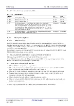
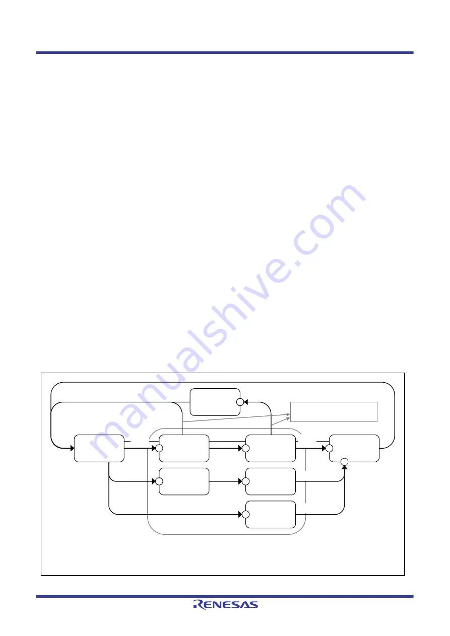
is a diagram of control transfer stage transitions in the USB. The USB controls the control transfer
sequence and generates control transfer stage transition interrupts. The control transfer stage transition interrupts can be
enabled or disabled individually using INTENB0. The transfer stage to which a transition was made can be confirmed
using the INTSTS0.CTSQ[2:0] flags.
Control transfer stage transition interrupts are generated only when the function controller is selected.
The control transfer sequence errors are listed below. If an error occurs, the DCPCTR.PID[1:0] bits are set to 1xb
(STALL response).
During control read transfer:
An OUT token is received while no data has been transferred for the IN token at the data stage.
An IN token is received at the status stage.
A data packet with PID = DATA0 is received at the status stage.
During control write transfer:
An IN token is received while no ACK response has been returned for the OUT token at the data stage.
A data packet with PID = DATA0 is received for the first data packet at the data stage.
An OUT token is received at the status stage
During no-data control transfers:
An OUT token is received at the status stage.
At the control write transfer data stage, if the number of receive data exceeds the wLength value of the USB request, it
cannot be recognized as a control transfer sequence error. At the control read transfer status stage, packets other than
zero-length packets are received by an ACK response and the transfer ends normally.
When a CTRT interrupt occurs in response to a sequence error (INTSTS0.CTRT = 1), CTSQ[2:0] = 110b value is
retained until the CTRT flag = 0 is written from the system (the interrupt status is cleared). Therefore, while CTSQ[2:0]
= 110b is being held, the CTRT interrupt that ends the setup stage will not be generated even if a new USB request is
received. (The USB retains the setup stage end, and after the interrupt status has been cleared by software, a setup stage
end interrupt is generated.)
Figure 32.13
Control Transfer Stage Transitions
ACK
transmission
Error
detection
Setup
token reception
ACK
transmission
OUT token
IN token
Note:
CTRT interrupts
(1) Setup stage completed
(2) Control read transfer status stage transition
(3) Control write transfer status stage transition
(4) Control transfer completed
(5) Control transfer sequence error
Setup token reception
Error detection and setup token
reception are valid at all stages
in the box.
ACK
trans-
mission
CTSQ = 110b
control transfer
sequence error
5
Setup token reception
CTSQ = 000b
setup stage
CTSQ = 001b
control read
data stage
1
CTSQ = 010b
control read
status stage
2
CTSQ = 011b
control write
data stage
1
CTSQ = 100b
control write
status stage
3
CTSQ = 101b
no data control
status stage
1
CTSQ = 000b
idle stage
4
4
ACK
trans-
mission
ACK
reception
ACK
reception

