R01UH0823EJ0100 Rev.1.00
Page 734 of 1823
Jul 31, 2019
RX23W Group
26. 8-Bit Timer (TMR)
26.2.5
Timer Counter Control Register (TCCR)
Note 1. To use an external count clock, set the corresponding pin function. For details, refer to section 21, I/O Ports and section 22,
Multi-Function Pin Controller (MPC).
Note 2. This bit is reserved in TMR0. The bit is read as 0. Writing to these bits is not possible.
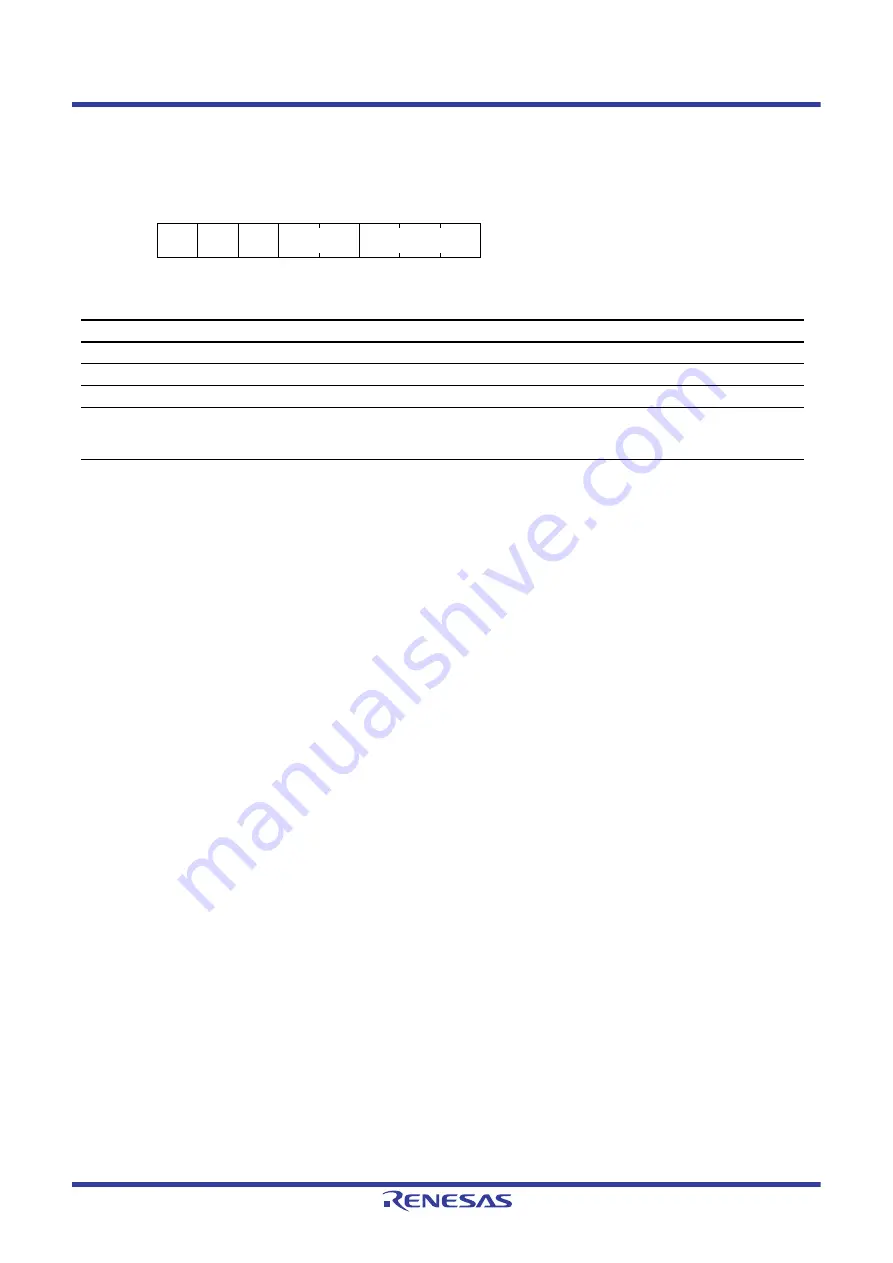
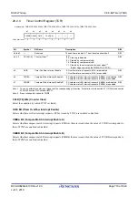
TCCR register is a 8-bit register used to configure the basic operation of the counter. Two TCCR registers can be
accessed simultaneously by accessing the address of the even channel TCCR register in 16-bit units.
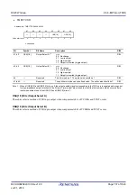
CKS[2:0] Bits (Clock Select)
CSS[1:0] Bits (Clock Source Select)
The CKS[2:0] and CSS[1:0] bits select a clock. For details, see
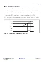
TMRIS Bit (Timer Reset Detection Condition Select)
This bit is enabled when the TCR.CCLR[1:0] bits are 11b (cleared by external counter reset signal) and selects the
condition for detecting counter reset (level or edge).
Address(es): TMR0.TCCR 0008 820Ah, TMR1.TCCR 0008 820Bh, TMR2.TCCR 0008 821Ah, TMR3.TCCR 0008 821Bh,
TMR01.TCCR 0008 820Ah, TMR23.TCCR 0008 821Ah
b7
b6
b5
b4
b3
b2
b1
b0
TMRIS
—
—
CSS[1:0]
CKS[2:0]
Value after reset:
0
0
0
0
0
0
0
0
Bit
Symbol
Bit Name
Description
R/W
b2 to b0
Clock Select*
R/W
b4, b3
Clock Source Select
R/W
b6, b5
—
Reserved
These bits are read as 0. The write value should be 0.
R/W
b7
Timer Reset Detection Condition
Select*
0: Cleared at rising edge of the external counter reset
signal
1: Cleared when the external counter reset signal is high
R/W


