Section 7. Installation
comprehensive treatment of field-calibration topics. The most comprehensive
resource to date covering use of
FieldCal()
and
FieldCalStrain()
is
RTDAQ
software documentation available at
www.campbellsci.com
. Be aware of the following precautions:
•
The CR1000 does not check for out-of-bounds values in mode variables.
•
Valid mode variable entries are
1
or
4
.
Before, during, and after calibration, one of the following codes will be stored in
the
CalMode
variable:
Table 28.
FieldCal() Codes
Value Returned
State
-1
Error in the calibration setup
-2
Multiplier set to
0
or
NAN
; measurement =
NAN
-3
Reps
is set to a value other than
1
or the size of
MeasureVar
0
No calibration
1
Ready to calculate (
KnownVar
holds the first of a two point
calibration)
2
Working
3
First point done (only applicable for two point calibrations)
4
Ready to calculate (
KnownVar
holds the second of a two-point
calibration)
5
Working (only applicable for two point calibrations)
6
Calibration complete
7.9.12.4.1 One-Point Calibrations (Zero or Offset)
Zero operation applies an offset of equal magnitude but opposite sign. For
example, when performing a zeroing operation on a measurement of 15.3, the
value –15.3 will be added to subsequent measurements.
Offset operation applies an offset of equal magnitude and same sign. For
example, when performing an offset operation on a measurement of 15.3, the
value 15.3 will be added to subsequent measurements.
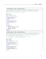
See
FieldCal() Zero or Tare (Opt 0) Example
(p. 214)
and
FieldCal() Offset (Opt 1)
Example
(p. 216)
for demonstration programs:
1. Use a separate
FieldCal()
instruction and variables for each sensor to be
calibrated. In the CRBasic program , put the
FieldCal()
instruction
immediately below the associated measurement instruction.
2. Set mode variable = 0 or 6 before starting.
3. Place the sensor into zeroing or offset condition.
4. Set
KnownVar
variable to the offset or zero value.
5. Set mode variable =
1
to start calibration.
212
Summary of Contents for CR1000
Page 2: ......
Page 4: ......
Page 6: ......
Page 32: ......
Page 36: ......
Page 38: ......
Page 40: ......
Page 60: ...Section 4 System Quickstart Figure 16 PC200W View Line Graph 60 ...
Page 96: ......
Page 98: ...98 ...
Page 302: ......
Page 453: ...Section 8 Operation Figure 115 Using the Keyboard Display 453 ...
Page 456: ...Section 8 Operation Figure 118 Real Time Custom 456 ...
Page 457: ...Section 8 Operation 8 8 1 3 Final Memory Tables Figure 119 Final Memory Tables 457 ...
Page 458: ...Section 8 Operation 8 8 2 Run Stop Program Figure 120 Run Stop Program 458 ...
Page 460: ...Section 8 Operation Figure 122 File Edit 460 ...
Page 461: ...Section 8 Operation 8 8 4 PCCard Memory Card Display Figure 123 PCCard CF Card Display 461 ...
Page 478: ......
Page 506: ......
Page 536: ......
Page 636: ......
Page 642: ......
Page 644: ......
Page 676: ......
Page 677: ......

