Section 8. Operation
for those terminals and serial ports configurable for either TTL or true RS-232
communications. Use of the
CS I/O
port for true RS-232 communications
requires use of an interface device. See the appendix
CS I/O Serial Interfaces
(p.
If additional serial inputs are required, serial input expansion modules can be
connected. See the appendix
Serial I/O Modules List
(p. 646).
Serial data are
usually captured as text strings, which are then parsed (split up) as defined in the
CRBasic program.
Note
C
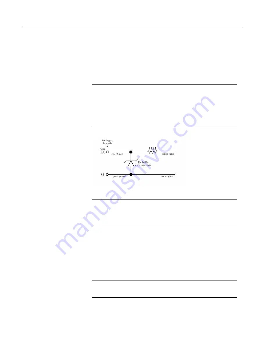
terminals configured as Tx transmit only 0 to 5 Vdc logic. However,
C
terminals configured as Rx read most true RS-232 signals. When connecting
serial sensors to a
C
terminal configured as Rx, the sensor power consumption
may increase by a few milliamps due to voltage clamps in the CR1000. An
external resistor may need to be added in series to the Rx line to limit the current
drain, although this is not advisable at very high baud rates. Figure Circuit to
Limit
C
Terminal RS-232 Input to 5 Volts
(p. 363)
shows a circuit that limits
voltage to 5 Vdc.
Figure 97. Circuit to Limit C Terminal Input to 5 Vdc
8.1.6.2 SDI-12 Sensor Support — Details
Related Topics:
•
SDI-12 Sensor Support — Overview
(p. 72)
•
SDI-12 Sensor Support — Details
(p. 363)
•
Serial I/O: SDI-12 Sensor Support — Programming Resource
(p. 267)
•
SDI-12 Sensor Support — Instructions
(p. 555)
SDI-12 is a communication protocol developed to transmit digital data from smart
sensors to data-acquisition units. It is a simple protocol, requiring only a single
communication wire. Typically, the data-acquisition unit also supplies power (12
Vdc and ground) to the SDI-12 sensor.
SDI12Recorder()
instruction
communicates with SDI-12 sensors on terminals configured for SDI-12 input.
See the table
CR1000 Terminal Definitions
(p. 76)
to determine those terminals
configurable for SDI-12 communications.
8.1.7 Field Calibration — Overview
Related Topics:
•
Field Calibration — Overview
(p. 73)
•
Field Calibration — Details
(p. 210)
Calibration increases accuracy of a measurement device by adjusting its output, or
the measurement of its output, to match independently verified quantities.
Adjusting sensor output directly is preferred, but not always possible or practical.
363
Summary of Contents for CR1000
Page 2: ......
Page 4: ......
Page 6: ......
Page 32: ......
Page 36: ......
Page 38: ......
Page 40: ......
Page 60: ...Section 4 System Quickstart Figure 16 PC200W View Line Graph 60 ...
Page 96: ......
Page 98: ...98 ...
Page 302: ......
Page 453: ...Section 8 Operation Figure 115 Using the Keyboard Display 453 ...
Page 456: ...Section 8 Operation Figure 118 Real Time Custom 456 ...
Page 457: ...Section 8 Operation 8 8 1 3 Final Memory Tables Figure 119 Final Memory Tables 457 ...
Page 458: ...Section 8 Operation 8 8 2 Run Stop Program Figure 120 Run Stop Program 458 ...
Page 460: ...Section 8 Operation Figure 122 File Edit 460 ...
Page 461: ...Section 8 Operation 8 8 4 PCCard Memory Card Display Figure 123 PCCard CF Card Display 461 ...
Page 478: ......
Page 506: ......
Page 536: ......
Page 636: ......
Page 642: ......
Page 644: ......
Page 676: ......
Page 677: ......


