Section 7. Installation
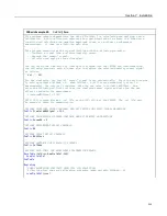
'This program demonstrates the multiplier calibration with the following procedure:
' -- Simulate a signal from a water content sensor.
' -- Measure the 'sensor' signal.
' -- Calculate and apply an offset.
'
'You can set up the simulation by loading this program into the CR1000 and interconnecting
'the following terminals with a jumper wire to simulate a water content sensor signal as
'follows:
'
Vx1
---
SE
1
'For the simulation, the value of the calibration standard and the initial 'sensor' signal
'are set automatically. Start the multiplier routine by setting variable CalMode = 1. When
'CalMode = 6 (occurs automatically after 10 measurements), the routine is complete. Note the
'new value in variable WCMultiplier. Now enter a new value in the simulated sensor signal
'as follows and note how the new multiplier scales the measurement:
' SimulatedWaterContentSignal = 350
'NOTE: This program places a .cal file on the CPU: drive of the CR1000. The .cal file must
'be erased to reset the demonstration.
'DECLARE SIMULATED SIGNAL VARIABLE AND SET INITIAL MAGNITUDE
Public
SimulatedWaterContentSignal = 175
'mV, second setting is 700 mV
'DECLARE CALIBRATION STANDARD VARIABLE AND SET MAGNITUDE
Public
KnownWC = 10
'% by Volume, second setting is 35%
'DECLARE MEASUREMENT RESULT VARIABLE.
Public
WC
'DECLARE MULTIPLIER RESULT VARIABLE AND SET INITIAL MAGNITUDE
Public
WCMultiplier = 1
'DECLARE VARIABLE FOR FieldCal() CONTROL
Public
CalMode
'DECLARE DATA TABLE FOR RETRIEVABLE CALIBRATION RESULTS
DataTable
(CalHist,NewFieldCal,200)
SampleFieldCal
EndTable
BeginProg
'LOAD CALIBRATION CONSTANTS FROM FILE CPU:CALHIST.CAL
'Effective after the zero calibration procedure (when variable CalMode = 6)
LoadFieldCal
(true)
Scan
(100,mSec,0,0)
'SIMULATE SIGNAL THEN MAKE THE MEASUREMENT
'Multiplier calibration is applied when variable CalMode = 6
ExciteV(
Vx1,SimulatedWaterContentSignal,0)
VoltSE
(WC,1,mV2500,1,1,0,250,WCMultiplier,0)
222
Summary of Contents for CR1000
Page 2: ......
Page 4: ......
Page 6: ......
Page 32: ......
Page 36: ......
Page 38: ......
Page 40: ......
Page 60: ...Section 4 System Quickstart Figure 16 PC200W View Line Graph 60 ...
Page 96: ......
Page 98: ...98 ...
Page 302: ......
Page 453: ...Section 8 Operation Figure 115 Using the Keyboard Display 453 ...
Page 456: ...Section 8 Operation Figure 118 Real Time Custom 456 ...
Page 457: ...Section 8 Operation 8 8 1 3 Final Memory Tables Figure 119 Final Memory Tables 457 ...
Page 458: ...Section 8 Operation 8 8 2 Run Stop Program Figure 120 Run Stop Program 458 ...
Page 460: ...Section 8 Operation Figure 122 File Edit 460 ...
Page 461: ...Section 8 Operation 8 8 4 PCCard Memory Card Display Figure 123 PCCard CF Card Display 461 ...
Page 478: ......
Page 506: ......
Page 536: ......
Page 636: ......
Page 642: ......
Page 644: ......
Page 676: ......
Page 677: ......

