V0IN inputs:
LSE & 3P4W=TRUE & (IN > minimum) & (IN > I1*8%) & (V0 > minimum)
LSE & 3P4W=TRUE & (IG > minimum) & (V0 > minimum)
(VX > minimum)
)
g the SP-60FL command.
d current thresholds that are
use Loss Detection Status from the Relay
Test: 60FL=FA
V0IG inputs:
Test: 60FL=FA
VXIN inputs:
Test: (IG > minimum) & (IN > I1*8%) &
VXIG inputs:
Test: (IG > minimum) & (VX > minimum
I
Block and V Block settings are made usin
The 60FL element detects fuse loss and loss of potential by using voltage an
expressed as a percentage of the nominal voltage and current values. See Section 3,
Input and Output
Functions
, for information on changing the nominal voltage and current values using the SG-NOM
command.
Retrieving F
ough the ASCII command interface using the RG-
VIRTUAL SWITCHES
The status of the logic variable can be determined thr
STAT (report general-status) command. See Section 6,
Reporting and Alarm Functions, General Status
Reporting
, for more information. The status can also be determined using BESTCOMS
Metering
screen.
43 - Virtual Selector Switches
ntial System has eight virtual selector switches that can provide manual
d interface. Control
343, 443, 543, 643,
The BE1-CDS240 Current Differe
control, locally and remotely, without using physical switches and/or interposing relays. Each virtual
switch can be set for one of three modes of operation to emulate virtually any type of binary (two position)
switch. An example would be an application that requires a ground cutoff switch. The traditional approach
might be to install a switch on the panel and wire the output to a contact sensing input on the relay or in
series with the ground trip output of the relay. Instead, a virtual switch can be used to reduce costs with
the added benefit of being able to operate the switch both locally through the HMI and remotely from a
substation computer or through a modem connection to a remote operator's console.
The state of the switches can be controlled from the optional HMI or ASCII comman
actions can be set by the BESTlogic mode setting. When set for
On/Off/Pulse
, each switch can be
controlled to open (logic 0), close (logic 1), or pulse such that the output toggles from its current state to
the opposite state and then returns. Additional modes allow the switch operation to be restricted. In
On/Off
, the switch emulates a two-position selector switch, and only open and close commands are
accepted. In
Off/Momentary On
, a momentary close, spring-return switch is emulated and only the pulse
command is accepted. Because switch status information is saved in nonvolatile memory, the relay
powers up with the switches in the same state as when the relay was powered down.
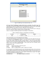
Each virtual selector switch element (see Figure 4-64) has one output:
43, 143, 243,
and
743
. The output is TRUE when the switch is in the closed state; the output is FALSE when the switch
is the open state. Since both the output and the inverse of the output of these switches can be used as
many times as desired in your programmable logic, they can emulate a switch with as many normally
open and normally closed decks as desired.
Figure 4-64. Virtual Selector Switches Logic Block
9365200990 Rev F
BE1-CDS240 Protection and Control
4-67
Summary of Contents for BE1-CDS240
Page 2: ......
Page 8: ...vi BE1 CDS240 Introduction 9365200990 Rev F This page intentionally left blank ...
Page 38: ...1 28 BE1 CDS240 General Information 9365200990 Rev F This page intentionally left blank ...
Page 40: ...ii BE1 CDS240 Quick Start 9365200990 Rev F This page intentionally left blank ...
Page 152: ...ii BE1 CDS240 Metering 9365200990 Rev F This page intentionally left blank ...
Page 226: ...iv BE1 CDS240 Application 9365200990 Rev F This page intentionally left blank ...
Page 286: ...ii BE1 CDS240 Security 9365200990 Rev F This page intentionally left blank ...
Page 290: ...9 4 BE1 CDS240 Security 9365200990 Rev F This page intentionally left blank ...
Page 292: ...ii BE1 CDS240 Human Machine Interface 9365200990 Rev F This page intentionally left blank ...
Page 306: ...10 14 BE1 CDS240 Human Machine Interface 9365200990 Rev F This page intentionally left blank ...
Page 308: ...ii BE1 CDS240 ASCII Command Interface 9365200990 Rev F This page intentionally left blank ...
Page 342: ...11 34 BE1 CDS240 ASCII Command Interface 9365200990 Rev F This page intentionally left blank ...
Page 349: ...Figure 12 5 Horizontal Rack Mount Front View 9365200990 Rev F BE1 CDS240 Installation 12 5 ...
Page 361: ...Figure 12 17 Typical DC Connection Diagrams 9365200990 Rev F BE1 CDS240 Installation 12 17 ...
Page 372: ...12 28 BE1 CDS240 Installation 9365200990 Rev F This page intentionally left blank ...
Page 468: ...13 92 BE1 CDS240 Testing and Maintenance 9365200990 Rev F This page intentionally left blank ...
Page 512: ...14 42 BE1 CDS240 BESTCOMS Software 9365200990 Rev F This page intentionally left blank ...
Page 544: ...ii BE1 CDS240 Terminal Communication 9365200990 Rev F This page intentionally left blank ...
Page 550: ...ii BE1 CDS240 Settings Calculations 9365200990 Rev F This page intentionally left blank ...
Page 578: ...D 28 BE1 CDS240 Settings Calculations 9365200990 Rev F This page intentionally left blank ...
Page 579: ......


