


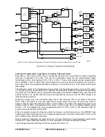


This logic is useful in a situation where two transformers feed a single bus or two busses have a bus tie
between them. The feeder and bus relays must be coordinated for the situation where only one source is
in service (bus tie open or one transformer out of service). However, when both sources are in service,
such as when the bus tie is closed, each bus relay sees only half of the current for a fault. This results in
poor sensitivity and slow clearing time for the bus relays.
Example 2:
Adapting the logic in different setting groups.
The logic in most of the preprogrammed logic schemes can be varied in each of the different setting
groups. This is accomplished by disabling functions by setting their primary settings at zero. More
sophisticated modification of the logic in each of the different setting groups is possible by using the
active setting group logic variables SG0, SG1, SG2, and SG3 in the BESTlogic expressions.
Output Contact Seal-in
Trip contact seal-in circuits have historically been provided with electromechanical relays. These seal-in
circuits consisted of a dc coil in series with the relay trip contact and a seal-in contact in parallel with the
trip contact. The seal-in feature serves several purposes for the EM relays. One is to provide mechanical
energy to drop the target. Second is to carry the dc tripping current from the induction disk contact that
may not have significant closing torque for a low resistance connection. The third is to prevent the relay
contact from dropping out until the current has been interrupted by the 52a contacts in series with the trip
coil. If the tripping contact opens before the dc current is interrupted, the contact may be damaged. The
first two of these items are not an issue for solid-state relays, but the third item is an issue.
To prevent the output relay contacts from opening prematurely, a 200 millisecond hold timer can be
selected with the SG-HOLDn=1 command. (See Table 8-38.) Refer to Section 3,
Input and Output
Functions, Outputs, Programmable Hold Timer,
for more information on this feature. If the protection
engineer desires seal-in logic with feedback from the breaker position logic, he/she can provide this
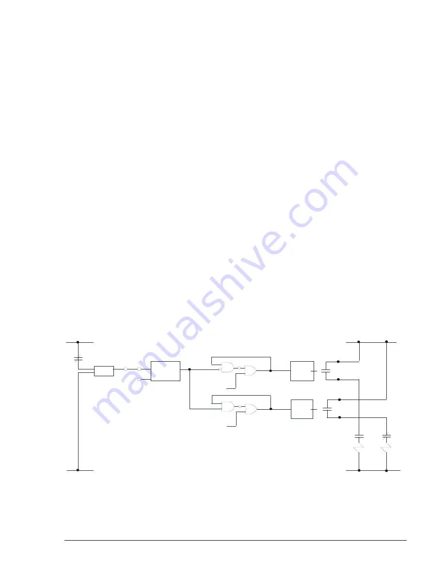
feature by modifying the BESTlogic expression for the tripping output. To do this, use one of the general
purpose timers, 62, or 162 and set it for mode 1 (Pickup/Dropout Timer). Set the timer logic so that it is
initiated by the breaker position input, and set the timer for two cycles pickup and two cycles dropout.
Then AND the timer output with the tripping output (VO1) and OR it into the expression for the tripping
output. The same can be done for the closing output. See Figure 8-17 for the seal-in logic diagram and
Seal-in Logic Table 8-38 that follows. This table is based on the CDS240-BATX-A-BE preprogrammed
logic scheme.
OUTPUT
LOGIC
OPTO
OUTPUT
LOGIC
INI
62
BLK
IN1
52b
+
+
62
-
TRIPPING
LOGIC
52TC
CLOSING
LOGIC
52CC
OUT2
OUT1
+
-
52a
52b
52TC
52CC
D2590-10
03-23-98
VO1
VO2
VO7
VO6
Figure 8-17. Output Seal-in Logic Diagram
9365200990 Rev F
BE1-CDS240 Application
8-55
Summary of Contents for BE1-CDS240
Page 2: ......
Page 8: ...vi BE1 CDS240 Introduction 9365200990 Rev F This page intentionally left blank ...
Page 38: ...1 28 BE1 CDS240 General Information 9365200990 Rev F This page intentionally left blank ...
Page 40: ...ii BE1 CDS240 Quick Start 9365200990 Rev F This page intentionally left blank ...
Page 152: ...ii BE1 CDS240 Metering 9365200990 Rev F This page intentionally left blank ...
Page 226: ...iv BE1 CDS240 Application 9365200990 Rev F This page intentionally left blank ...
Page 286: ...ii BE1 CDS240 Security 9365200990 Rev F This page intentionally left blank ...
Page 290: ...9 4 BE1 CDS240 Security 9365200990 Rev F This page intentionally left blank ...
Page 292: ...ii BE1 CDS240 Human Machine Interface 9365200990 Rev F This page intentionally left blank ...
Page 306: ...10 14 BE1 CDS240 Human Machine Interface 9365200990 Rev F This page intentionally left blank ...
Page 308: ...ii BE1 CDS240 ASCII Command Interface 9365200990 Rev F This page intentionally left blank ...
Page 342: ...11 34 BE1 CDS240 ASCII Command Interface 9365200990 Rev F This page intentionally left blank ...
Page 349: ...Figure 12 5 Horizontal Rack Mount Front View 9365200990 Rev F BE1 CDS240 Installation 12 5 ...
Page 361: ...Figure 12 17 Typical DC Connection Diagrams 9365200990 Rev F BE1 CDS240 Installation 12 17 ...
Page 372: ...12 28 BE1 CDS240 Installation 9365200990 Rev F This page intentionally left blank ...
Page 468: ...13 92 BE1 CDS240 Testing and Maintenance 9365200990 Rev F This page intentionally left blank ...
Page 512: ...14 42 BE1 CDS240 BESTCOMS Software 9365200990 Rev F This page intentionally left blank ...
Page 544: ...ii BE1 CDS240 Terminal Communication 9365200990 Rev F This page intentionally left blank ...
Page 550: ...ii BE1 CDS240 Settings Calculations 9365200990 Rev F This page intentionally left blank ...
Page 578: ...D 28 BE1 CDS240 Settings Calculations 9365200990 Rev F This page intentionally left blank ...
Page 579: ......


