EDH0162En1040 – 06/99
5.6
MM4005
Trajectory Functions Tutorial
To eliminate the burden of calculating the angle matching, use as much as
possible the commands that define a straight line by one coordinate, X or
Y, and by the entry angle (also referred to as the tangent). This simplifies
the user’s programming task and lets the controller find the best fit for the
trajectory elements.
5.4.1
Defining Lines
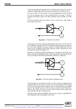
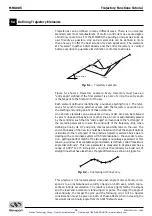
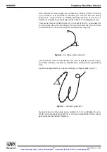
There are two ways to define a line of a trajectory. The first one is to speci-
fy the X-Y end coordinates (the starting point is always the end point of the
previous element). This is the most common procedure found in the indus-
try (Fig. 5.3).
Fig. 5.3
— Line to X-Y.
As described previously, when using this method the user must make an
extra effort in making sure the maximum discontinuity angle is not exceeded.
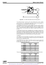
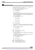
A second mode of defining a straight line in a trajectory is illustrated in
Figure 5.4.
Fig. 5.4
— Line to X or Y.
Using the previous element’s exit angle (tangent), the controller can execute
a line to the specified X coordinate (Fig. 5.4-a) or Y coordinate (Fig. 5.4-b).
This method simplifies the programming job and guaranties the best trajec-
tory elements fit.
5.4.2
Defining Arcs
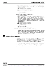
Arcs can also be defined in two different ways. The first one is more conven-
tional, where a radius and the sweep angle will define the arc (Fig 5.5).
Fig. 5.5
— Arc defined with radius and angle.
X
5.4-a
Y
5.4-b
X, Y
Artisan Technology Group - Quality Instrumentation ... Guaranteed | (888) 88-SOURCE | www.artisantg.com

