EDH0162En1040 – 06/99
8.20
MM4005
Appendix D — Motion Program Examples
Example 2
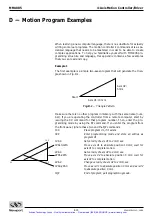
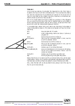
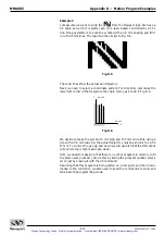
In the previous example, to generate the diagonal line (the third motion
segment) both axes must move simultaneously. This is achieved by taking
two special precautions: the commands are placed on the same line to
insure a good start synchronization and the velocities are modified such
that the motions will end in the same time.
But, if you would measure very accurately the precision of this diagonal
line, you would notice some errors due to imperfect start synchronization
and an incorrect acceleration ratio. In other words, we achieved this dual-
axes motion with two independent single-axis motions.
To eliminate these motion errors, we need to use the axes synchronization
(linear interpolation) feature. The improved program will have the follow-
ing listing:
2XX
Erase program #2, if it exists.
2EP
Enter programming mode and store all entries as
program #2.
1VA4
Set velocity of axis #1 to 4 mm/sec.
1PA10,1WS
Move axis #1 to absolute position 10 mm; wait for
axis #1 to complete motion.
2VA4
Set velocity of axis #1 to 4 mm/sec.
2PA5,2WS
Move axis #2 to absolute position 5 mm; wait for
axis #2 to complete motion.
1SY1,2SY1
Declare axes #1 and #2 synchronized.
1PA0,2PA0,SE,WS
Set axis #1 destination to 0 mm and axis #2 destina-
tion to 0 mm; start synchronous motion; wait for
motion to complete.
1SY0,2SY0
Declare axes #1 and #2 non-synchronized.
2QP
End of program #2; quit programming mode.
Notice that there is no need to set the velocities before the synchronized
(interpolated) motion. The controller automatically calculates them to get the
best accuracy possible, without exceeding the pre-set individual velocities.
Also, when finished with an interpolated motion, always return the axes to
the non-synchronized mode.
0, 0
10, 0
10, 5
Artisan Technology Group - Quality Instrumentation ... Guaranteed | (888) 88-SOURCE | www.artisantg.com

