2-36
MPC8240 Integrated Processor User’s Manual
Clocking
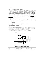
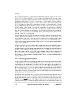
The peripheral logic DLL is synchronized to SDRAM_SYNC_IN. Figure 2-2 shows how
the PCI_SYNC_IN and SDRAM_SYNC_IN signals are independent of each other. These
signals are supplied for synchronization of external components on the system board. For
minimum skew between PCI_SYNC_OUT and the PCI_CLKn signals, the trace length on
PCI_SYNC_IN should be designed so that it is the same as the trace lengths on the
PCI_CLKn signals to their driven components. Similarly, for minimum skew, the loop
length on SDRAM_SYNC_IN should be designed so that it is the same as the loop lengths
on the SDRAM_CLKn signals to their driven components. For example, for minimum
skew, if an SDRAM device has a 5-inch trace, the loop trace should be 5 inches in length.
Note that a system designer may deliberately vary the loop lengths in order to introduce a
distinct amount of skew between SDRAM_SYNC_OUT (PCI_SYNC_OUT) and the
SDRAM_CLKn (PCI_CLKn) signals.
There are cases in which the DLL tap point may need to be explicitly altered. In this case,
the DLL_EXTEND bit of PMCR2 can be written to shift the lock range of the DLL by half
of an SDRAM clock cycle. Note that this bit should only be written during system
initialization and should not be altered during normal operation. See MPC8240 Hardware
Specification for more information about the use of DLL_EXTEND and the locking ranges
supplied by the MPC8240.
There is a bit (DLL_RESET) in the AMBOR register that controls the initial tap point of
the DLL. Note that although this bit is cleared after a hard reset, it must be explicitly set
and then cleared by software during initialization in order to guarantee correct operation of
the DLL and the SDRAM_CLK[0:3] signals (if they are used). Therefore, care must be
taken when using SDRAM_CLK[0:3] to clock peripheral logic, as these clocks are not
guaranteed to be operational until DLL_RESET is toggled in softtware as described above.
See Section 4.9, “Address Map B Options Register—0xE0,” for more information about
the DLL_RESET bit.
2.3.3 Clock Synchronization
The MPC8240 has the ability to provide the entire system with various system clocks based
on PCI_SYNC_IN and the PLL_CFG[0:4] setting at reset. All of these clocks are
synchronized by the internal logic of the MPC8240. In systems that use an external PLL to
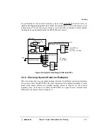
generate the memory system clocks and do not depend on the SDRAM_CLK[0:3] signals
(shown in Figure 2-4), PCI_SYNC_IN must be phase-aligned with the input to the external
PLL, and the MPC8240 system logic PLL should be programmed to have the same bus
ratio as the external PLL in order to synchronize the internal processor bus and the internal
peripheral logic to the memory interface.
In situations where the setting of PLL_CFG[0:4] creates a half-clock ratio between the PCI
bus and processor bus, and an external PLL is being used to generate the memory system
clocks, then SDRAM_SYNC_IN must be driven by the external PLL the same way as the
SDRAM devices. In addition, clock flipping logic must be enabled through the reset
configuration pin QACK. This flipping ensures that the processor bus and internal logic will
Summary of Contents for MPC8240
Page 1: ...MPC8240UM D Rev 1 1 2001 MPC8240 Integrated Processor User s Manual ...
Page 38: ...xviii MPC8240 Integrated Processor User s Manual TABLES Table Number Title Page Number ...
Page 48: ...xlviii MPC8240 Integrated Processor User s Manual Acronyms and Abbreviations ...
Page 312: ...6 94 MPC8240 Integrated Processor User s Manual ROM Flash Interface Operation ...
Page 348: ...7 36 MPC8240 Integrated Processor User s Manual PCI Host and Agent Modes ...
Page 372: ...8 24 MPC8240 Integrated Processor User s Manual DMA Register Descriptions ...
Page 394: ...9 22 MPC8240 Integrated Processor User s Manual I2O Interface ...
Page 412: ...10 18 MPC8240 Integrated Processor User s Manual Programming Guidelines ...
Page 454: ...12 14 MPC8240 Integrated Processor User s Manual Internal Arbitration ...
Page 466: ...13 12 MPC8240 Integrated Processor User s Manual Exception Latencies ...
Page 516: ...16 14 Watchpoint Trigger Applications ...
Page 538: ...B 16 MPC8240 Integrated Processor User s Manual Setting the Endian Mode of Operation ...
Page 546: ...C 8 MPC8240 Integrated Processor User s Manual ...
Page 640: ...INDEX Index 16 MPC8240 Integrated Processor User s Manual ...

