Chapter 2. Signal Descriptions and Clocking
2-39
Configuration Signals Sampled at Reset
reset configuration signals are actually sampled 3 clock cycles before the negation of the
HRST_CTRL and HRST_CPU signals, as described in the MPC8240 Hardware
Specification. For more information about the timing requirements of these configuration
signals relative to the negation of the reset signals, refer to the MPC8240 Hardware
Specification.
The reset configuration signals serve multiple purposes, and the signal names do not reflect
the functionality of the signals as they are used for reset configuration. The values on these
signals during reset are interpreted to be logic one or zero, regardless of whether the signal
name is defined as active-low. Most of the reset configuration signals have internal pull-up
resistors so that if the signals are not driven, the default value is high (a one), as shown in
the table. The PLL_CFG[0:4] signals do not have pull-up resistors and must be driven high
or low during the reset period.
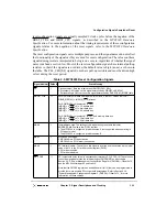
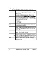
Table 2-5. MPC8240 Reset Configuration Signals
Signal Name(s)
Default
State Meaning
AS
1
Clock out select. Sets the initial value of PMCR1[CKO_SEL]:
0 Processor CKO; value on this signal determined by HID0[ECLK,SBCLK].
1 Peripheral logic CKO; value on this signal determined by PMCR1[CKO_MODE] field.
MDL[0], FOE
11
Sets the initial ROM bank 0 data path width, DBUS_SIZE[0:1], values in MCCR1.
DBUS_SIZE[0:1] = (MDL[0], FOE) at reset.
For ROM/FLASH chip select #0 (RCS0),
(MDL[0] = 0, FOE = 0) = 32-bit data bus.
(MDL[0] = x, FOE = 1) = 8-bit data bus.
(MDL[0] = 1, FOE = 0) = 64-bit data bus.
For ROM/FLASH chip select #1 (RCS1) and memory data bus,
(MDL[0] = 0, FOE = x) = 32-bit data bus.
(MDL[0] = 1, FOE = x) = 64-bit data bus.
MAA0
1
Initial address map. The setting of this signal during reset sets the initial
ADDRESS_MAP value in the PICR1 register.
0 The MPC8240 is configured for address map A (not supported when operating in
PCI agent mode).
1 The MPC8240 is configured for address map B.
MAA1
1
MPC8240 host mode
0 MPC8240 is a PCI agent device
1 MPC8240 is a PCI master (host) device
MAA2
1
PCI arbiter disable—The value on this signal is inverted and then written as the initial
value of bit 15 in the PCI arbiter control register (PACR).
0 PCI arbiter enabled
1 PCI arbiter disabled
MCP, CKE
11
PCI output hold delay value (in nanoseconds) relative to PCI_SYNC_IN. The values on
these two signals determine the initial settings of PMCR2[6:5] as described in
Section 4.3.2, “Power Management Configuration Register 2 (PMCR2)—Offset 0x72,”
and the MPC8240 Hardware Specification.
Note that the PMCR2 register has an additional bit (bit 4) that can be programmed to
provide four more possible PCI output hold delay values. Refer to Section 4.3.2,
“Power Management Configuration Register 2 (PMCR2)—Offset 0x72,” for more
information on these settings
Summary of Contents for MPC8240
Page 1: ...MPC8240UM D Rev 1 1 2001 MPC8240 Integrated Processor User s Manual ...
Page 38: ...xviii MPC8240 Integrated Processor User s Manual TABLES Table Number Title Page Number ...
Page 48: ...xlviii MPC8240 Integrated Processor User s Manual Acronyms and Abbreviations ...
Page 312: ...6 94 MPC8240 Integrated Processor User s Manual ROM Flash Interface Operation ...
Page 348: ...7 36 MPC8240 Integrated Processor User s Manual PCI Host and Agent Modes ...
Page 372: ...8 24 MPC8240 Integrated Processor User s Manual DMA Register Descriptions ...
Page 394: ...9 22 MPC8240 Integrated Processor User s Manual I2O Interface ...
Page 412: ...10 18 MPC8240 Integrated Processor User s Manual Programming Guidelines ...
Page 454: ...12 14 MPC8240 Integrated Processor User s Manual Internal Arbitration ...
Page 466: ...13 12 MPC8240 Integrated Processor User s Manual Exception Latencies ...
Page 516: ...16 14 Watchpoint Trigger Applications ...
Page 538: ...B 16 MPC8240 Integrated Processor User s Manual Setting the Endian Mode of Operation ...
Page 546: ...C 8 MPC8240 Integrated Processor User s Manual ...
Page 640: ...INDEX Index 16 MPC8240 Integrated Processor User s Manual ...

