


Appendix E. Processor Core Register Summary
E-5
PowerPC Register Set
E.1.1.3.2 Condition Register CR1 Field Definition
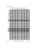
The bit settings for the CR1 field are shown in Table E-2.
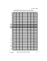
E.1.1.3.3 Condition Register CRn Field—Compare Instruction
For a compare instruction the bits of the specified field are interpreted as shown in
Table E-3.
2
Zero (EQ)—This bit is set when the result is zero.
3
Summary overflow (SO)—This is a copy of the final state of XER[SO] at
the completion of the instruction.
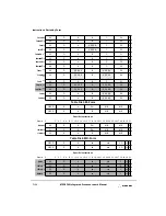
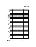
Table E-2. Bit Settings for CR1 Field of CR
CR1 Bit
Description
4
Floating-point exception (FX)—This is a copy of the final state of
FPSCR[FX] at the completion of the instruction.
5
Floating-point enabled exception (FEX)—This is a copy of the final
state of FPSCR[FEX] at the completion of the instruction.
6
Floating-point invalid exception (VX)—This is a copy of the final state
of FPSCR[VX] at the completion of the instruction.
7
Floating-point overflow exception (OX)—This is a copy of the final state
of FPSCR[OX] at the completion of the instruction.
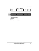
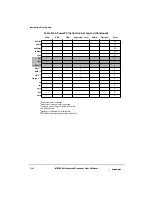
Table E-3. CRn Field Bit Settings for Compare Instructions
CRn Bit
1
Description
0
Less than or floating-point less than (LT, FL).
For integer compare instructions: rA < SIMM or rB (signed comparison) or
rA < UIMM or rB (unsigned comparison).
For floating-point compare instructions: frA < frB.
1
Greater than or floating-point greater than (GT, FG).
For integer compare instructions: rA > SIMM or rB (signed comparison) or
rA > UIMM or rB (unsigned comparison).
For floating-point compare instructions: frA > frB.
2
Equal or floating-point equal (EQ, FE).
For integer compare instructions: rA = SIMM, UIMM, or rB.
For floating-point compare instructions: frA = frB.
3
Summary overflow or floating-point unordered (SO, FU).
For integer compare instructions:This is a copy of the final state of XER[SO]
at the completion of the instruction.
For floating-point compare instructions: One or both of frA and frB is a Not a
Number (NaN).
Notes:
1
Here, the bit indicates the bit number in any one of the 4-bit subfields, CR0–CR7.
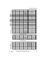
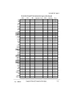
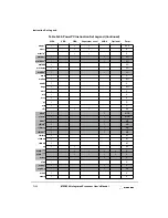
Table E-1. Bit Settings for CR0 Field of CR (Continued)
CR0 Bit
Description
Summary of Contents for MPC8240
Page 1: ...MPC8240UM D Rev 1 1 2001 MPC8240 Integrated Processor User s Manual ...
Page 38: ...xviii MPC8240 Integrated Processor User s Manual TABLES Table Number Title Page Number ...
Page 48: ...xlviii MPC8240 Integrated Processor User s Manual Acronyms and Abbreviations ...
Page 312: ...6 94 MPC8240 Integrated Processor User s Manual ROM Flash Interface Operation ...
Page 348: ...7 36 MPC8240 Integrated Processor User s Manual PCI Host and Agent Modes ...
Page 372: ...8 24 MPC8240 Integrated Processor User s Manual DMA Register Descriptions ...
Page 394: ...9 22 MPC8240 Integrated Processor User s Manual I2O Interface ...
Page 412: ...10 18 MPC8240 Integrated Processor User s Manual Programming Guidelines ...
Page 454: ...12 14 MPC8240 Integrated Processor User s Manual Internal Arbitration ...
Page 466: ...13 12 MPC8240 Integrated Processor User s Manual Exception Latencies ...
Page 516: ...16 14 Watchpoint Trigger Applications ...
Page 538: ...B 16 MPC8240 Integrated Processor User s Manual Setting the Endian Mode of Operation ...
Page 546: ...C 8 MPC8240 Integrated Processor User s Manual ...
Page 640: ...INDEX Index 16 MPC8240 Integrated Processor User s Manual ...


