Chapter 4. Configuration Registers
4-13
PCI Interface Configuration Registers
Reads to this register behave normally. Writes are slightly different in that bits can be
cleared, but not set. A bit is cleared whenever the register is written, and the data in the
corresponding bit location is a 1. For example, to clear bit 14 and not affect any other bits
in the register, write the value 0b0100_0000_0000_0000 to the register.
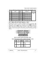
Figure 4-4. PCI Status Register—0x06
Table 4-6 describes the bit settings for the PCI status register.
Table 4-6. Bit Settings for PCI Status Register—0x06
Bits
Name
Reset
Value
Description
15
Detected parity error
0
This bit is set whenever the MPC8240 detects an address or data parity
error, even if parity error handling is disabled (as controlled by bit 6 in
the PCI command register).
14
Signaled system error
0
This bit is set whenever the MPC8240 asserts SERR.
13
Received
master-abort
0
This bit is set whenever the MPC8240, acting as the PCI master,
terminates a transaction (except for a special-cycle) using master-abort.
12
Received target-abort
0
This bit is set whenever an MPC8240-initiated transaction is terminated
by a target-abort.
11
Signaled target-abort
0
This bit is set whenever the MPC8240, acting as the PCI target, issues
a target-abort to a PCI master.
10–9
DEVSEL timing
00
These bits are hardwired to 0b00, indicating that the MPC8240 uses
fast device select timing.
8
Data parity detected
0
This bit is set upon detecting a data parity error. Three conditions must
be met for this bit to be set:
• The MPC8240 detected a parity error.
• MPC8240 was acting as the bus master for the operation in which
the error occurred.
• Bit 6 (parity error response) in the PCI command register was set.
7
Fast back-to-back
capable
1
This bit is hardwired to 1, indicating that the MPC8240 (as a target) is
capable of accepting fast back-to-back transactions.
6
—
0
This bit is reserved.
5
66-MHz capable
1
This bit is read-only and indicates that the MPC8240 is capable of
66-MHz PCI bus operation.
4–0
—
0_0000
These bits are reserved.
Reserved
0
0_0 0 0 0
15
14
13
12
11
10
9
8
7
6
5
4
0
Signaled Target-Abort
DEVSEL Timing
Data Parity Detected
Fast Back-to-Back Capable
66-MHz Capable
Received Target-Abort
Received Master-Abort
Signaled System Error
Detected Parity Error
Summary of Contents for MPC8240
Page 1: ...MPC8240UM D Rev 1 1 2001 MPC8240 Integrated Processor User s Manual ...
Page 38: ...xviii MPC8240 Integrated Processor User s Manual TABLES Table Number Title Page Number ...
Page 48: ...xlviii MPC8240 Integrated Processor User s Manual Acronyms and Abbreviations ...
Page 312: ...6 94 MPC8240 Integrated Processor User s Manual ROM Flash Interface Operation ...
Page 348: ...7 36 MPC8240 Integrated Processor User s Manual PCI Host and Agent Modes ...
Page 372: ...8 24 MPC8240 Integrated Processor User s Manual DMA Register Descriptions ...
Page 394: ...9 22 MPC8240 Integrated Processor User s Manual I2O Interface ...
Page 412: ...10 18 MPC8240 Integrated Processor User s Manual Programming Guidelines ...
Page 454: ...12 14 MPC8240 Integrated Processor User s Manual Internal Arbitration ...
Page 466: ...13 12 MPC8240 Integrated Processor User s Manual Exception Latencies ...
Page 516: ...16 14 Watchpoint Trigger Applications ...
Page 538: ...B 16 MPC8240 Integrated Processor User s Manual Setting the Endian Mode of Operation ...
Page 546: ...C 8 MPC8240 Integrated Processor User s Manual ...
Page 640: ...INDEX Index 16 MPC8240 Integrated Processor User s Manual ...


