16-2
Watchpoint Interface Signal Description
•
Two watchpoints with 58-bit triggers (signal-by-signal comparison on peripheral
logic address and control bus) that control a single TRIG_OUT signal.
•
TRIG_IN signal for explicitly enabling and disabling the watchpoint facility and for
exiting hold state
•
A bit-wise programmable ANDing mask of a watchpoint trigger for each watchpoint
•
The ability to trigger only on the nth watchpoint match where n is
user-programmable for each watchpoint
•
One-shot scan mode for generating only one trigger match and then automatically
disabling the watchpoint facility
•
Continuous scan mode for generating multiple trigger matches
•
Single, waterfall, OR, and AND NOT modes that determine the interaction between
watchpoints #1 and #2 (including their counter registers)
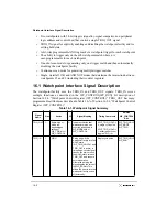
16.1 Watchpoint Interface Signal Description
The watchpoint facility uses the TRIG_IN and TRIG_OUT signals. TRIG_IN serves
multiple functions as described in the WP_CONTROL[WP_RUN] bit description of
Section 16.2.4, “Watchpoint Control Register (WP_CONTROL).” TRIG_OUT has many
programmable attributes as described in Table 16-7 of Section 16.2.4, “Watchpoint Control
Register (WP_CONTROL).”
Table 16-1. Watchpoint Signal Summary
Signal
Name
Pins
Active
I/0
Signal Meaning
Timing Comments
Related
WP_CONTROL
Bits
TRIG_OUT
1
Active high or
active low
depending on
setting of
WP_TRIG bit of
WP_CONTROL
O
Indicates that the final
watchpoint match has
occurred as defined in
WP_MODE field of
WP_CONTROL.
If WP_TRIG_HOLD =
0, single cycle pulse.
If WP_TRIG_HOLD =
1, asserted until user
toggles TRIG_IN.
WP_TRIG_HOLD
WP_MODE
WP_TRIG
TRIG_IN
1
HIGH
I
Rising edge: If the
watchpoint facility is in the
HOLD state
(WP_TRIG_HOLD=1 and
TRIG_OUT is active), a
rising edge on this signal
causes the device to exit
the HOLD state, release
TRIG_OUT, and resume
normal operation.
Otherwise, pulsing this
signal toggles the value of
the WP_RUN bit. This
allows the user to turn the
watchpoint facility on and
off externally.
Single cycle pulse
WP_TRIG_HOLD
WP_RUN
Summary of Contents for MPC8240
Page 1: ...MPC8240UM D Rev 1 1 2001 MPC8240 Integrated Processor User s Manual ...
Page 38: ...xviii MPC8240 Integrated Processor User s Manual TABLES Table Number Title Page Number ...
Page 48: ...xlviii MPC8240 Integrated Processor User s Manual Acronyms and Abbreviations ...
Page 312: ...6 94 MPC8240 Integrated Processor User s Manual ROM Flash Interface Operation ...
Page 348: ...7 36 MPC8240 Integrated Processor User s Manual PCI Host and Agent Modes ...
Page 372: ...8 24 MPC8240 Integrated Processor User s Manual DMA Register Descriptions ...
Page 394: ...9 22 MPC8240 Integrated Processor User s Manual I2O Interface ...
Page 412: ...10 18 MPC8240 Integrated Processor User s Manual Programming Guidelines ...
Page 454: ...12 14 MPC8240 Integrated Processor User s Manual Internal Arbitration ...
Page 466: ...13 12 MPC8240 Integrated Processor User s Manual Exception Latencies ...
Page 516: ...16 14 Watchpoint Trigger Applications ...
Page 538: ...B 16 MPC8240 Integrated Processor User s Manual Setting the Endian Mode of Operation ...
Page 546: ...C 8 MPC8240 Integrated Processor User s Manual ...
Page 640: ...INDEX Index 16 MPC8240 Integrated Processor User s Manual ...

