10-16
MPC8240 Integrated Processor User’s Manual
Programming Guidelines
generate SCK so that the device driving SDA can finish its transaction, the following
procedure can be used on the MPC8240:
1. Disable the I
2
C and set the master bit by setting I2CCR to 0x20.
2. Enable the I
2
C by setting I2CCR to 0xA0.
3. Read the I2CDR.
4. Return the MPC8240 to slave mode by setting I2CCR to 0x80.
10.4.7 Slave Mode Interrupt Service Routine
In the slave interrupt service routine, the module addressed as a slave should be tested to
check if a calling of its own address has just been received. If I2CSR[MAAS] = 1, software
should set the transmit/receive mode select bit (I2CCR[MTX]) according to the R/W
command bit (I2CSR[SRW]). Writing to I2CCR clears I2CSR[MAAS] automatically. The
only time I2CSR[MAAS] is read as set is from the interrupt handler at the end of that
address cycle where an address match occurred; interrupts resulting from subsequent data
transfers will have I2CSR[MAAS] = 0. A data transfer can then be initiated by writing to
I2CDR for slave transmits or dummy reading from I2CDR in slave-receive mode. The slave
drives SCL low between byte transfers. SCL is released when the I2CDR is accessed in the
required mode.
10.4.7.1 Slave Transmitter and Received Acknowledge
In the slave transmitter routine, the received acknowledge bit (I2CSR[RXAK]) must be
tested before sending the next byte of data. The master signals an end-of-data by not
acknowledging the data transfer from the slave. When no acknowledge is received
(I2CSR[RXAK] = 1), the slave transmitter interrupt routine must clear I2CCR[MTX] to
switch the slave from transmitter to receiver mode. A dummy read of I2CDR then releases
SCL so that the master can generate a STOP condition. See Section 10.4.8, “Interrupt
Service Routine Flowchart.”
10.4.7.2 Loss of Arbitration and Forcing of Slave Mode
When a master loses arbitration (see Section
10.2.6, “Arbitration Procedure”),
I2CSR[MAL] is set indicating loss of arbitration; I2CCR[MSTA] is cleared (changing the
master to slave mode), and an interrupt occurs (if enabled) at the falling edge of the 9th
clock of this transfer. Thus, the slave interrupt service routine should test I2CSR[MAL]
first, and the software should clear I2CSR[MAL] if it is set.
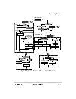
10.4.8 Interrupt Service Routine Flowchart
Figure 10-8 shows an example algorithm for an I
2
C interrupt service routine. Deviation
from the flowchart may result in unpredictable I
2
C bus behavior except that unlike what is
shown in the flowchart, in slave receive mode, the interrupt service routine may need to set
I2CCR[TXAK] when the next-to-last byte is to be accepted. It is recommended that a sync
instruction follow each I
2
C register read or write to guarantee in-order instruction
execution.
Summary of Contents for MPC8240
Page 1: ...MPC8240UM D Rev 1 1 2001 MPC8240 Integrated Processor User s Manual ...
Page 38: ...xviii MPC8240 Integrated Processor User s Manual TABLES Table Number Title Page Number ...
Page 48: ...xlviii MPC8240 Integrated Processor User s Manual Acronyms and Abbreviations ...
Page 312: ...6 94 MPC8240 Integrated Processor User s Manual ROM Flash Interface Operation ...
Page 348: ...7 36 MPC8240 Integrated Processor User s Manual PCI Host and Agent Modes ...
Page 372: ...8 24 MPC8240 Integrated Processor User s Manual DMA Register Descriptions ...
Page 394: ...9 22 MPC8240 Integrated Processor User s Manual I2O Interface ...
Page 412: ...10 18 MPC8240 Integrated Processor User s Manual Programming Guidelines ...
Page 454: ...12 14 MPC8240 Integrated Processor User s Manual Internal Arbitration ...
Page 466: ...13 12 MPC8240 Integrated Processor User s Manual Exception Latencies ...
Page 516: ...16 14 Watchpoint Trigger Applications ...
Page 538: ...B 16 MPC8240 Integrated Processor User s Manual Setting the Endian Mode of Operation ...
Page 546: ...C 8 MPC8240 Integrated Processor User s Manual ...
Page 640: ...INDEX Index 16 MPC8240 Integrated Processor User s Manual ...


