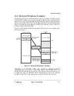
Chapter 3. Address Maps
3-15
Address Translation
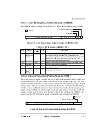
3.3.3.1 Local Memory Base Address Register (LMBAR)
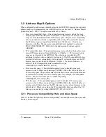
The LMBAR, shown in Figure 3-8 and Table 3-8, defines the inbound memory window.
Figure 3-8. Local Memory Base Address Register (LMBAR)—0x10
3.3.3.2 Inbound Translation Window Register (ITWR)
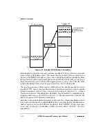
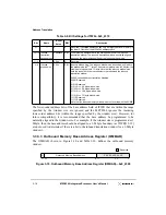
The ITWR, shown in Figure 3-9 and Table 3-9, defines the inbound translation window and
the inbound window size. The inbound window size in the ITWR sets the size of both the
inbound translation window in local memory and the inbound memory window in PCI
memory space. Software can alter the inbound translation base address in the ITWR during
run-time to access different portions of local memory. Because the inbound memory base
address in the LMBAR should be aligned to the inbound window size in the ITWR, the
inbound window size should not be changed without also updating the LMBAR. As a
general rule, the ITWR should be programmed before programming the LMBAR.
Figure 3-9. Inbound Translation Window Register (ITWR)
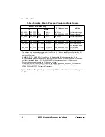
Table 3-8. Bit Settings for LMBAR—0x10
Bits
Name
Reset
Value
R/W
Description
31–12 Inbound
memory base
address
0x0000_0
R/W
Indicates the base address where the inbound memory window resides.
The inbound memory window should be aligned based on the
granularity specified by the inbound window size specified in the ITWR.
Note that the EUMB area must be selected first, then the ITWR
programmed, and then these bits can be set.
11–4
—
All 0s
R
Reserved; the MPC8240 only allows a minimum of a 4KByte window.
3
Prefetchable
1
R
Indicates that the space is prefetchable.
2–1
Type
00
R
The inbound memory window may be located anywhere within the
32-bit PCI address space.
0
Memory
space
indicator
0
R
Indicates PCI memory space.
Inbound Memory Base Address
0 0 0 0 0 0 0 0
1
00
0
31
12 11
4
3
2
1
0
Reserved
Prefetchable
Memory Space Indicator
Type
0
Inbound Translation Base Address
0 0 0 0 0 0 0
31
30
12 11
5
4
0
Reserved
Inbound Window Size
Summary of Contents for MPC8240
Page 1: ...MPC8240UM D Rev 1 1 2001 MPC8240 Integrated Processor User s Manual ...
Page 38: ...xviii MPC8240 Integrated Processor User s Manual TABLES Table Number Title Page Number ...
Page 48: ...xlviii MPC8240 Integrated Processor User s Manual Acronyms and Abbreviations ...
Page 312: ...6 94 MPC8240 Integrated Processor User s Manual ROM Flash Interface Operation ...
Page 348: ...7 36 MPC8240 Integrated Processor User s Manual PCI Host and Agent Modes ...
Page 372: ...8 24 MPC8240 Integrated Processor User s Manual DMA Register Descriptions ...
Page 394: ...9 22 MPC8240 Integrated Processor User s Manual I2O Interface ...
Page 412: ...10 18 MPC8240 Integrated Processor User s Manual Programming Guidelines ...
Page 454: ...12 14 MPC8240 Integrated Processor User s Manual Internal Arbitration ...
Page 466: ...13 12 MPC8240 Integrated Processor User s Manual Exception Latencies ...
Page 516: ...16 14 Watchpoint Trigger Applications ...
Page 538: ...B 16 MPC8240 Integrated Processor User s Manual Setting the Endian Mode of Operation ...
Page 546: ...C 8 MPC8240 Integrated Processor User s Manual ...
Page 640: ...INDEX Index 16 MPC8240 Integrated Processor User s Manual ...

