Copyright © Siemens AG 2016. All rights reserved
116
ERTEC 200P-2 Manual
Technical data subject to change
Version 1.0
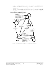
The running job can be interrupted when the job-enabling bit (JOB_EN) of
the Job Control register is reset from ‘1’ to ‘0’.
The running and all interrupted jobs can be cancelled, when the job-
resetting bit (JOB_RESET) in the Job Control register is set.
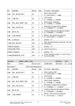
Control of the job by HW
The running of a DMA job dedicated to transfers from HW peripheral to
memory or from memory to HW peripheral, is controlled by HW through the
use of the input signals “HW Job Start” and “HW DMA request”. See the de-
scription above.
Furthermore, also the job controlled by HW can be interrupted and cancelled
via SW, just as in the case of the SW control of the job, described above.
2.3.4.1.5.3 Job finished
When a DMA job is finished, the GDMA controller generates a DMA interrupt request.
This interrupt request generation can be enabled/disabled for each job, using bit
INTR_EN of the Job Control registers. When the DMA interrupt is generated, a “job fin-
ished” bit in the Interrupt State register is set.
2.3.4.1.5.4 Monitoring of GDMA Controller Status
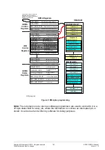
For monitoring of the GDMA controller via SW, important feedback information about the
status of the GDMA is indicated by the DMA_IRQ interrupt request signal and by the
GDMA Status Register, see above.
2.3.4.1.6 Memory
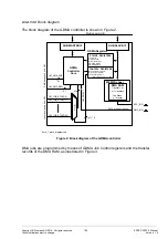
The GDMA RAM is used to store the DMA transfer list and the job stack. It can be used
either as an internal GDMA RAM or as an external RAM. This feature is HW configurable
by means of a constant in the VHDL code.
The external RAM is accessible from the GDMA through its AHB Master interface. The
address space of the GDMA RAM is configurable by means of GDMA Control registers
(LIST_ADDR and LIST_SIZE). Thus the GDMA controller can use any RAM that is ac-
cessible via the AHB bus.
The internal GDMA RAM is accessible from the CPU through the AHB Slave interface of
the GDMA only with word accesses (byte and halfword write accesses not possible).
From the GDMA controller is accessible through its AHB Master interface. Note that the
datapath from the GDMA controller core to the GDMA RAM is: GDMA controller core ->
AHB Master of the GDMA -> Multi-layer AHB Bus -> AHB Slave of the GDMA -> RAM
Wrapper -> RAM. Thus the access algorithm is the same for both GDMA RAM configura-
tions. The address space of the internal GDMA RAM is also configurable by means of
GDMA Control registers (LIST_ADDR and LIST_SIZE).
The implementation of the GDMA for the ERTEC 200P the configuration with an internal
GDMA RAM is the same as in Triton2. The GDMA RAM has size of ((n+1) x 16 Byte) +
((j+1) x 16 Byte), where “n” is the index of the last transfer from the transfer list and “j” is
the index of the last job stack. The configuration for ERTEC 200P is n = 255 and J = 31.
For this configuration the internal GDMA SRAM is organized in 1152 x 32 Bit
.

