Copyright © Siemens AG 2016. All rights reserved
282
ERTEC 200P-2 Manual
Technical data subject to change
Version 1.0
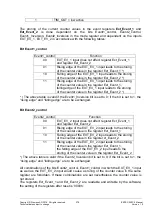
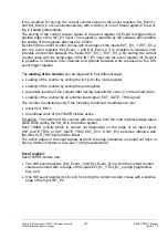
2.3.10.3.6
Operating rules
Initialization sequence, modifications of the mode register
Initialization sequence:
1. Stop counter (CLK_EN=0 = setting after reset)
2. Write load register (counter is not loaded if CLK_EN=0)
3. Write mode register with Init_bit = ’1’:
counter is loaded with load register
4. Start counter (CLK_EN=1).
The initialization sequence also has to be carried out with each modification of the mode
register to prevent any side effects when changing the operating mode.
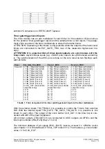
Cascading of TIMER modules:
The TIMER modules can be cascaded with each other, provided that the timer output of
the lower-value counter(s) is fed back to the TIMER_TOP module via the
EXTERNAL_INPUTS signals and is selected as GATE_TRIG signal at the high-order
timer).
Proceed as follows for that:
1. Program the multiplexer in such a way that each high-order counter has the timer
output of the low-order counter as GATE_TRIG signal.
2. Define the interrupt evaluation in such a way that the interrupt of the high-order
counter is evaluated. The interrupt of the low-order counter(s) must not be evaluat-
ed.
3. Set the operating modes (mode register, prescaler register) of the cascaded TIMER
modules the same way (not absolutely necessary but reasonable if the cascaded
TIMER modules are to count with the same clock).
4. When reading the counter value, make sure that the data is consistent, e.g. write
SW event trigger register bits for all cascaded TIMER modules in order to take over
the values of these TIMER modules synchronously into the Int_Event registers;
then, read the Int_Event registers of these TIMER modules.
5. The setting of the preselectors for the cascaded TIMER modules has to be adapted
to the application (same preselectors are reasonable).
Note on the Toggle mode
For the first count/load clock after having set the Toggle mode or after reset or after ac-
tive Init_bit, it cannot be predicted if the count/load clock causes a loading of the counter
with the reload value or a down-counting (depends on the level of the count/load clock
during the setting or during the active Init_bits).
If this information is important for the software, it has to poll the level and value of the
counter during the first count/load clock.
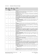
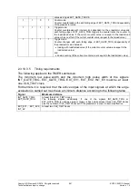
Be careful when storing into event registers!
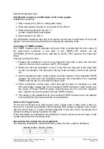
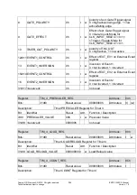
The following combination of the bits Event2_control, Event1_control is forbidden:
Event2_control
Event1_control
01
01
01
11

