Copyright © Siemens AG 2016. All rights reserved
313
ERTEC 200P-2 Manual
Technical data subject to change
Version 1.0
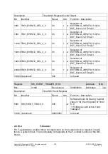
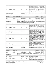
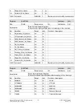
the FIFO is enabled, the TXFE bit is
set when the transmit FIFO is empty.
8
Ring_Indicator
0h
rh
Ring indicator. This bit is the comple-
ment of the UART ring indicator
(nUARTRI) modem status input. That
is, the bit is 1 when the modem status
input is 0.
31dt9 <unused>
000000h r
Reserved, read as zero.
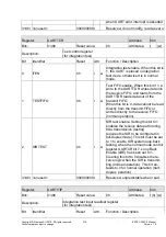
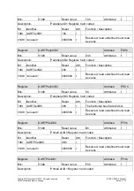
Register:
USRTILPR
Address:
20h
Bits:
31dt0
Reset value:
0h
Attributes: r (w)
Description:
8-bit-low-power divisor value. These bits are cleared to 0 at reset.
Bit
Identifier
Reset
Attr.
Function / Description
7dt0 USRTILPR
00h
r
w 8-bit low-power divisor value.
31dt8 <unused>
000000h r
Reserved, read as zero.
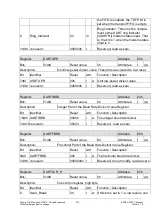
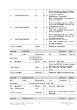
Register:
UARTIBRD
Address:
24h
Bits:
31dt0
Reset value:
0h
Attributes: r (w)
Description:
Integer Part of the Baud Rate Divisor Value Register
Bit
Identifier
Reset
Attr.
Function / Description
15dt0 UARTIBRD
0000h
r
w The integer baud rate divisor.
31dt16 <unused>
0000h
r
Reserved,
read as zero.
Register:
UARTFBRD
Address:
28h
Bits:
31dt0
Reset value:
0h
Attributes: r (w)
Description:
Fractional Part of the Baud Rate Divisor Value Register
Bit
Identifier
Reset
Attr.
Function / Description
5dt0 UARTFBRD
00h
r
w The fractional baud rate divisor.
31dt6 <unused>
0000000h r
Reserved, do not modify, read as zero.
Register:
UARTLCR_H
Address:
2Ch
Bits:
31dt0
Reset value:
0h
Attributes: r (w)
Description:
line control register, high byte
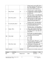
Bit
Identifier
Reset
Attr.
Function / Description
0
Send_Break
0h
r
w If this bit is set to 1, a low level is con-


