Copyright © Siemens AG 2016. All rights reserved
310
ERTEC 200P-2 Manual
Technical data subject to change
Version 1.0
2.3.10.5.3 Register Description
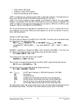
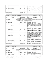
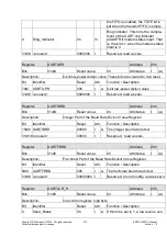
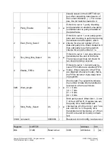
In the description of the UART IP, the read value of the unassigned register bits is in
some cases specified as "unpredictable. A read value of 0 is, however, implemented (see
UartApbif.vhd, assignment to the NextPRDATA signal).
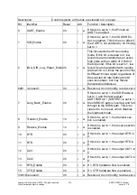
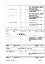
Module: /UART_PL011
Register:
UARTDR
Address:
0h
Bits:
31dt0
Reset value:
0h
Attributes: r(h) (w)
Description:
UARTDR is the data register
Receive (read) data character
Transmit (write) data character
Bit
Identifier
Reset
Attr.
Function / Description
7dt0 Data
00h
rh w
Receive (read) data character.
Transmit (write) data character.
8
Framing_Error
0h
rh
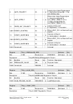
Framing error. When this bit is set to 1,
it indicates that the received character
did not have a valid stop
bit (a valid stop bit is 1).
In FIFO mode, this error is associated
with the character at the top of the
FIFO.
9
Parity_Error
0h
rh
Parity error. When this bit is set to 1, it
indicates that the parity of the received
data character does not match the
parity selected as defined by bits 2 and
7 of the UARTLCR_H register.
In FIFO mode, this error is associated
with the character at the top of the
FIFO.
10
Break_Error
0h
rh
Break error. This bit is set to 1 if a
break condition was detected, indicat-
ing that the received data input
was held LOW for longer than a full-
word transmission time (defined as
start, data, parity and stop bits).
In FIFO mode, this error is associated
with the character at the top of the
FIFO. When a break occurs, only one
0 character is loaded into the FIFO.
The next character is only enabled
after the receive data input goes to a 1
(marking state), and the next valid start
bit is received.

