Copyright © Siemens AG 2016. All rights reserved
351
ERTEC 200P-2 Manual
Technical data subject to change
Version 1.0
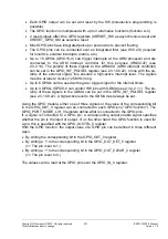
Each GPIO output can be set and reset by the SW (bit-selective programming is
possible).
The GPIO function is multiplexed with up to 3 alternative functions (function A-C).
2 reset signals affect the GPIO registers (XRESET_HW as asynchronous reset and
XRESET_GPIO_SM as selective reset.
Most GPIO pins have integrated pull-ups / pull-downs to prevent floating.
The GPIO pins can be connected over an integrated filter (see X5.5.2X) (required
for local IOs, external interrupts, alarms, etc.)
Up to 16 GPIOs (GPIO15-0) can trigger interrupts at the ARM processor and are
connected to the ARM interrupt controller for this purpose (IRQ32-47) (see
2.3.2.14). The polarity of these signals to the ARM-ICU (ARM interrupt controller)
can be set in the GPIO_INT_POLSEL register (see 2.3.10.9.22). In line with the po-
larity of the external signal, this ensures a high-active interrupt level. The signals
must be at least 2 clocks (125 MHz) long.
Up to 6 GPIOs can be used as the gate / trigger signal for the internal timers.
Up to 4 GPIOs (GPIO3-0 can control HW jobs with GDMA (see 2.3.4.2.1.1). The po-
larity of these signals to the GDMA can be set in the GPIO_INT_POLSEL register
(see 2.3.10.9.22). A high-active level to the GDMA must always be set.
Using the GPIO module, either one of three signals or the value of the corresponding bit
in the GPIO_OUT_0 register can be connected to each GPIO pin (
"GPIO function"
). The
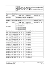
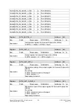
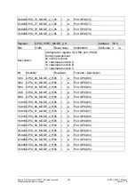
GPIO_PORT_MODE_L/H_0 registers define what is connected to the GPIO pins.
If a signal is connected to a GPIO pin, a corresponding output enable signal specifies
whether the pin is the input or output. If, on the other hand, the GPIO function is used for
a pin, this is specified with the GPIO_IOCTRL_0 register.
With the GPIO function, the output value of a GPIO pin can be defined in three different
ways:
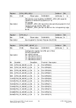
By writing the corresponding bit in the GPIO_OUT_0 register,
By writing a '1' to the corresponding bit in the GPIO_OUT_SET_0 register
(=> The pin is set to 1.)
By writing a '1' to the corresponding bit in the GPIO_OUT_CLEAR_0 register
(=> The pin is set to 0.)
The values can be read at the GPIO pins over the GPIO_IN_0 register.

