Copyright © Siemens AG 2016. All rights reserved
69
ERTEC 200P-2 Manual
Technical data subject to change
Version 1.0
In the address area of the EMC, the XCE_PER(3:0) outputs become active and the
Memory Controller waits for the XRDY_PER input signal. The confirmation delay monitor-
ing activated in the Async Wait Cycle Config Register (see chap. 2.3.5.8) after
((MAX_EX 1) x 16) AHB clock pulses creates an internal ready signal for the
Memory Controller and an IRQ. The IRQ will be removed when the QVZ monitoring is
disabled.
2.3.2.15
Interrupt sources for ARM-FIQ
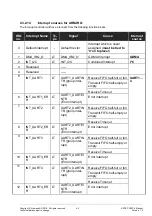
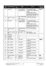
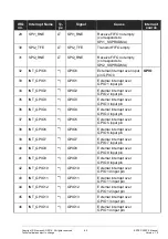
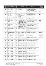
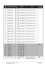
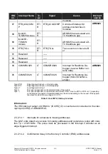
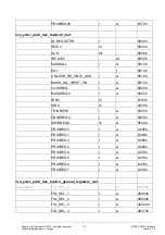
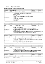
The Interrupt contoller will have interrupts from the following function blocks:
IRQ
no.
Interrupt Name
Ty-
pe
Signal
Cause
Interrupt
source
0
Default interrupt
-
Default Vector
Interrupt which is never as-
signed (
must be tied to '0' on
toplevel
)
1
FIQ_SEL_1
***)
Selectable interrupt from the INTA-
Sources about
FIQ_SEL_1
Register
2
FIQ_SEL_2
***)
Selectable interrupt from the INTA-
Sources about
FIQ_SEL_2
Register
3
FIQ_SEL_3
***)
Selectable interrupt from the INTA-
Sources about
FIQ_SEL_3
Register
4
FIQ_SEL_4
***)
Selectable interrupt from the INTA-
Sources about
FIQ_SEL_4
Register
5
FIQ_SEL_5
***)
Selectable interrupt from the INTA-
Sources about
FIQ_SEL_5
Register
6
FIQ_SEL_6
***)
Selectable interrupt from the INTA-
Sources about
FIQ_SEL_6
Register
7
FIQ_SEL_7
***)
Selectable interrupt from the INTA-
Sources about
FIQ_SEL_7
Register
Type ***)
This type is dependent on the Type of ARM-IRQ. It can be ET/F or ET/R or LT.
Table 10: Host INTB, Interrupt sources
Information:
The FIQ interrupt output of ARM-ICU (CUFIQ_O) is inverted and connected to the inter-
rupt input (nFIQ) of ARM926EJ-S.
2.3.2.15.1 High-priority Interrupts for Debugging
As effective RT debugging, the interrupts of the embedded ICE RT communication chan-
nel (
COMMRX926, COMMTX926)
or the interrupt of UART2 can be mapped over FIQ1 to
FIQ7. This allows interrupt routine debugging.

