Copyright © Siemens AG 2016. All rights reserved
33
ERTEC 200P-2 Manual
Technical data subject to change
Version 1.0
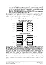
First, the 64 KByte segment that is already assigned to the I-TCM is completely
filled. The code image is then loaded to the D-TCM, in the correct order. After this
download, the final TCM926 configuration is set in
TCM926_MAP
(see
2.3.10.9.14). The secondary boot loader must also show the final configuration of
the TCM in the coprocessor register (CP15 c9) address range.
GDMA can also be used to load the code image to the D-TCM. This code image is
loaded to the D-TCM following booting by the host.
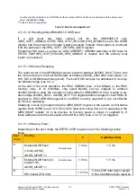
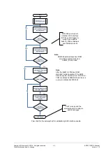
For booting from an external host, the primary boot loader creates a page for the D-TCM
(boot RAM) in the 8-page XHIF registers. The remaining pages can then be set up specif-
ically by the external host. It makes sense to set up additional pages for PN-IP, PER-IF,
EMC-SDRAM / EMC-SRAM, GDMA and APB peripherals.
Important: Please note that TCM block assignment in the ARM926 subsystem is re-
versed when you switch from D-TCM to I-TCM.
The ERTEC 200P has a three-stage boot model. The primary boot loader, stored in the
boot ROM, sets the hardware used to ensure that data can be read from the boot medi-
um and copied to the D-TCM of the ARM926. Only the boot medium used is initially con-
figured by the primary boot loader. The data copied comprises the secondary boot loader,
which copies the actual user program to the destination memory (SDRAM, TCM or
SRAM). This procedure keeps the primary boot loader very compact (max. 8 KByte are
allowed), which makes it easy to test. Complete configuration of the ERTEC 200P is only
implemented on a module-specific basis by the secondary boot loader or the user pro-
gram, as the user knows which hardware components their system requires and how
these are to be configured in the given environment. This also allows a wide range of
different compilers, without having to consider special features such as INIT or ROM
sections.

