Copyright © Siemens AG 2016. All rights reserved
306
ERTEC 200P-2 Manual
Technical data subject to change
Version 1.0
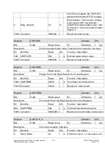
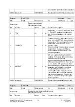
Ring Indicator (RI, Input)
Request to Send (RTS, Output)
Data Terminal Ready (DTR, Output)
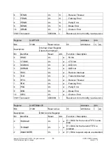
UART1-4 interfaces are available at the GPIO as alternate functions. The alternate func-
tion can be set with the SW in the GPIO registers (see 2.3.10.8.4.2).
UART1 incl. modem signals is fully available on GPIO95-32. UART2 can only enable
transmit, receive data, CTS and RTS. Only transmit and receive data are available from
UART3-4. UART3 is designed for debugging and is located on GPIO31-0. UART2 is also
located on GPIO31-0 and UART4 on GPIO95-32.
The IO-Link baud rates are supported; the residual error is < 0.01 %. A total of up to 4 IO-
Link interfaces can be used. GPIOs are also required for an IO-Link channel. The func-
tion is still to be defined.
2.3.10.5.1
UART Baud Rates
The baud rates are based on the APB clock (125 MHz). The baud rate is calculated using
the following formula (ideal baud rate):
BRI = F
UARTCLK
/ (BAUDDIV * 16) or BAUDDIV = (F
UARTCLK
/ (16 * BRI))
with BAUDDIV = (BRD
I
),(BRD
F
) (e.g. when BAUDIV = 1085 BRD
I
= 1, BRD
F
=
0.085)
BAUDDIV comprises an integer part (BRD
I
) and a fractional part (BRD
F
). The value (m)
for setting the fractional divider is calculating using the following formula:
m = integer ((BRD
F
* 64) + 0.5)
This produces the baud rate divisor used in UART:
BAUDDIV
real
= BRD
I
+ (m / 64)
This is used to calculate the actual baud rate of the UART using the following formula:
BR = F
UARTCLK
/ (BAUDDIV
real
* 16)
The baud rate error is calculated using the following formula:
E
P
= ((BR – BRI)/BRI) * 100 [%]
with: F
UARTCLK
= UART basic frequency = APB clock frequency (125 MHz)
BR
= baud rate
BRI
= ideal baud rate
BRD
I
= integer part of the baud rate divisor to be programmed
BRD
F
= fractional part of the baud rate divisor to be programmed
m
= fractional value to be set for the fractional divider (1/64)
E
P
= percentage baud rate deviation from the ideal baud rate
The table below shows the divisor values to be set for the baud rates and deviations from
the standard baud rates. The UART (incl. APB interface) with a clock of 125 MHz.


