Copyright © Siemens AG 2016. All rights reserved
369
ERTEC 200P-2 Manual
Technical data subject to change
Version 1.0
after reset (HW, SW or ARM926 watchdog reset). The boot ROM can also be addressed
in its original address range.
At the end of the boot operation (primary boot or secondary boot), the EMC interface
maps the asynchronous memory (
MEM_SWAP
= "01") or SDRAM (
MEM_SWAP
= "10")
to address 0x0000_0000h to allow the exception vector table for ARM926EJ-S to be
created in address range 0x0000_0000 – 0x0000_001F. The original address ranges for
boot ROM (in segment 4), EMC SDRAM (segment 2) and EMC memory (segment 3) are
not affected by memory swapping.
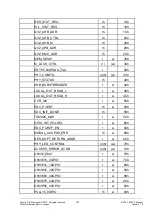
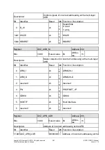
Swapping is done by programming the
MEM_SWAP
register. There is no swapping in
MEM_SWAP
with
reserved coding (or to be precise, no memory space is shown in segment 0). If these addresses are then
accessed at the AHB, a QVZ (see 2.3.2.5.1) is triggered.
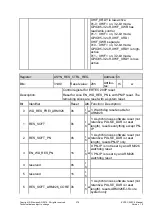
2.3.10.9.8 ARM Control Register
The following control information can be configured in this register:
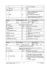
1. ARB: Setting for the arbitration procedure for ML-AHB (see 2.3.10.9.8.1)
2. ARM926 AHB-LOCK
2.3.10.9.8.1 AHB Arbiters
Each of the ML-AHB AHB arbiters uses the same arbitration procedure. The default set-
ting is round robin. A fixed priority assignment for the AHB masters could be used as an
alternative arbitration algorithm by programming the ARB bit in the SCRB register.
Switching to "fixed priority" fixes the priority set at ML-AHB when the arbitration type was
configured. This option should not, however, be implemented in the light of the dynamic
processes at the multi-layer AHB.
Using round robin as the arbitration procedure prevents the AHB masters from blocking
each other at the multi-layer AHB for a prolonged period of time.
2.3.10.9.9 PHY
Register
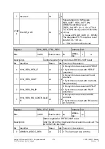
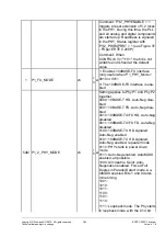
The configuration of both integrated PHYs can be set in the
PHY control register
PHY_CONFIG. This configuration is possible alongside the PHY configuration over SMI
(PN-IP). With PHY_LED_CONTROL, you can control whether the PHY-LED link status
and activity are to be controlled by the integrated PHY or SW. The LED status of the SW
is also saved.
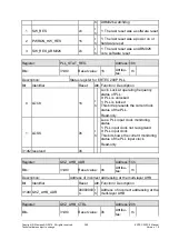
The readiness of both integrated PHYs can be read from the
PHY status register
PHY_STATUS.
2.3.10.9.10 AHB Burst Breaker Register
This register limits the maximum number of addresses of an AHM master in an ARM926
burst. A maximum limit of 256 addresses can be set. After the set number of addresses,
burst access by the ARM926 is interrupted by an IDLE sequence. This is function is re-
quired if an AHB master is blocking the bus for too long with burst access and preventing
another AHB master from accessing the slave in time (for details, see 2.3.2.3.3).
2.3.10.9.11 GPIO Control Register


