Copyright © Siemens AG 2016. All rights reserved
352
ERTEC 200P-2 Manual
Technical data subject to change
Version 1.0
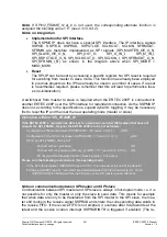
2.3.10.8.2
Integration of the GPIO Module
The GPIO module connects the top level modules to the GPIO pins. It is also connected
to the APB bus. The GPIO module is operated with the APB clock.
The feature of an internal GPIO "reset disable" is activated in ERTEC 200P (module
input: XRESET_HW connected to reset signal). Alongside the global reset
(XRESET_GPIO_SM), a selective reset in GPIO_SM is also possible.
The connection of the internal modules to the GPIO module (GPIO_XOE_F_A/B/C,
GPIO_OUT_F_A/B/C, GPIO_IN_F_A/B/C, GPIO_IN_F_A/B/C_BLOCK signals) is de-
scribed in the corresponding modules and in
GPIO assignment
.
GPIO
GPIO_OUT_F_A(k)
GPIO_IN_F_A(k)
GPIO_IN_F_A_BLOCK(k)
GPIO_XOE_F_A(k)
GPIO_OUT_F_B(k)
GPIO_IN_F_B(k)
GPIO_IN_F_B_BLOCK(k)
GPIO_XOE_F_B(k)
GPIO_OUT_F_C(k)
GPIO_IN_F_C(k)
GPIO_IN_F_C_BLOCK(k)
GPIO_XOE_F_C(k)
Pad
GPIO_DO(k)
GPIO_DI(k)
GPIO_XOE(k)
Module 2
Module 1
Module 3
Figure 44: GPIO, IO Circuit


