Copyright © Siemens AG 2016. All rights reserved
314
ERTEC 200P-2 Manual
Technical data subject to change
Version 1.0
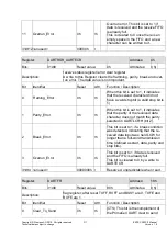
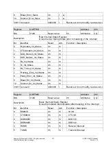
tinually output on the UARTTXD out-
put, after completing transmission of
the current character. (...) For normal
use, this bit must be cleared to 0.
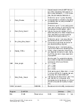
1
Parity_Enable
0h
r w
If this bit is set to 1, parity checking
and generation is enabled, else parity
is disabled and no parity bit added to
the data frame.
2
Even_Parity_Select
0h
r w
If this bit is set to 1, even parity gener-
ation and checking is performed during
transmission and reception, which
checks for an even number of 1s in
data and parity bits. When cleared to 0
then odd parity is performed which
checks for an odd number of 1s.
3
Two_Stop_Bits_Select
0h
r w
If this bit is set to 1, two stop bits are
transmitted at the end of the frame.
The receive logic does not check for
two stop bits being received.
4
Enable_FIFOs
0h
r w
If this bit is set to 1, transmit and re-
ceive FIFO buffers are enabled (FIFO
mode). When cleared to 0 the FIFOs
are disabled (character mode), that is,
the FIFOs become 1-byte-deep hold-
ing registers.
6dt5 Word_lenght
0h
r w
Word length. The select bits indicate
the number of data bits transmitted or
received in a frame as follows:
11 = 8 bits
10 = 7 bits
01 = 6 bits
00 = 5 bits.
7
Stick_Parity_Select
0h
r w
Stick parity select. When bits 1, 2, and
7 of the UARTLCR_H register are set,
the parity bit is transmitted and
checked as a 0. When bits 1 and 7 are
set, and bit 2 is 0, the parity bit is
transmitted and checked as a 1. When
this bit is cleared stick parity is disab-
led.
31dt8 <unused>
000000h r
Reserved, do not modify, read as zero.
Register:
UARTCR
Address:
30h
Bits:
31dt0
Reset value:
300h
Attributes: r (w)


