Chapter 9 SDRAM Controller
9-16
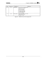
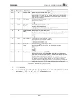
Bits Mnemonic Field
Name
Description
22:18
RC
Refresh Counter
Refresh Counter (Initial value: 00000, R/W)
This counter is decremented at each refresh. If the refresh circuit is activated and a
value other than “0” is loaded, this field becomes a down counter that stops at “0”. A
value other than “0” must be reloaded to start the countdown again. This is used
during memory initialization.
17
CASL
CAS Latency
CAS Latency (t
CASL
) (Initial value: 1, R/W)
Specifies the CAS latency.
0: 2 t
CK
1: 3 t
CK
16 DRB
Data Read
Bypass
Data Read Bypass (Initial value: 0, R/W)
Selects the Data Read path used.
0: Data Read latches to the register using the feedback clock.
1: Data Read bypasses the feedback clock latch.
15 DA
Active Command
Delay
Delay Activate (t
DA
) (Initial value: 1, R/W)
Specifies the delay from the row address to the bank active command. Setting this
bit to “1” sets up the row address two cycles before the active command is
executed.
0: 0 t
CK
1: 1 t
CK
14
SWB
Slow Write Burst
Slow Write Burst (t
SWB
) (Initial value: 1, R/W)
Specifies whether to perform Slow Write Burst.
0: Burst Write occurs at each 1 t
CK
1: Burst Write occurs at each 2 t
CK
13:12 DIA
Write Active
Period
Data In to Active(t
DAL
) (Initial value: 11, R/W)
Specifies the period from the last Write data to the Active command.
00: Reserved
01: 4 t
CK
10: 5 t
CK
11: 6 t
CK
11:0
RP
Refresh Period
Refresh Period (Initial value: 0x270, R/W)
Specifies the clock cycle count that generates the refresh cycle. Refresh is only
enabled when at least one SDRAM channel is enabled. Please program the Timing
Register before an arbitrary channel is enabled.
Default is 0x270. A refresh cycle occurs for each 7.8
µ
s@80 MHz in this situation.
The Refresh Cycle count clock is GBUSCLKF. The CCFG.RF value does not
change the frequency of GBUSCLKF. Therefore, it is not necessary to change this
register value even when CCFG.RF lowers the chip operation clock frequency.
Figure 9.4.2 SDRAM Timing Register (2/2)
*
1: t
CK
= Clock cycle
*
2: t
RC
is used during (i) refresh cycle time, (ii) single Read, (iii) two transfer burst Reads. The bank
cycle time is t
RAS
+ t
RP
+ 1t
CK
if t
RAS
+ t
RP
< t
RC
in the case of (ii) (iii).
Summary of Contents for TMPR4925
Page 1: ...64 Bit TX System RISC TX49 Family TMPR4925 Rev 3 0 ...
Page 4: ......
Page 15: ...Handling Precautions ...
Page 16: ......
Page 18: ...1 Using Toshiba Semiconductors Safely 1 2 ...
Page 40: ...3 General Safety Precautions and Usage Considerations 3 18 ...
Page 42: ...4 Precautions and Usage Considerations 4 2 ...
Page 43: ...TMPR4925 ...
Page 44: ......
Page 54: ...Chapter 1 Features 1 8 ...
Page 58: ...Chapter 2 Block Diagram 2 4 ...
Page 88: ...Chapter 4 Address Mapping 4 12 ...
Page 226: ...Chapter 8 DMA Controller 8 58 ...
Page 260: ...Chapter 9 SDRAM Controller 9 34 ...
Page 480: ...Chapter 15 Interrupt Controller 15 32 ...
Page 554: ...Chapter 19 Real Time Clock RTC 19 8 ...
Page 555: ...Chapter 20 Removed 20 1 20 Removed ...
Page 556: ...Chapter 20 Removed 20 2 ...
Page 564: ...Chapter 21 Extended EJTAG Interface 21 8 ...
Page 580: ...Chapter 22 Electrical Characteristics 22 16 ...
Page 588: ...Chapter 24 Usage Notes 24 2 ...


