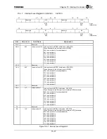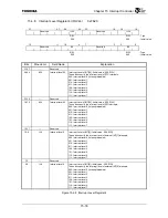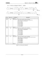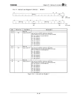
Chapter 15 Interrupt Controller
15-7
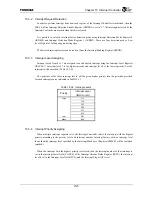
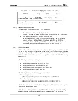
Table 15.3.3 Interrupt Notification to IP[7:2] of the CP0 Cause Register
TINTDIS IP[7]
IP[6:3]
IP[2]
0
(Internal Timer Interrupts: Valid)
Internal Timer
Interrupt Notification
IRCS.CAUSE[3:0] IRCS.IF
1
(Internal Timer Interrupts: Invalid)
IRCS.CAUSE[4:0] IRCS.IF
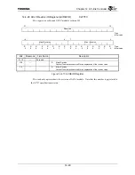
15.3.6 Clearing Interrupt Requests
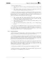
Interrupt requests are cleared according to the following process.
•
When the detection mode is set to the High level or Low level:
Operation is performed to deassert the request of a source that is asserting an interrupt request.
•
When the detection mode is set to Rising edge or Falling edge
Edge detection requests are cleared by first specifying the interrupt source of the interrupt
request to be cleared in the Edge Detection Clear Source field (EDCS0 or EDCS1) of the
Interrupt Edge Detection Clear Register (IREDC) then writing the resulting value when the
corresponding Edge Detection Clear Enable bit (EDCE0 or EDCE1) is set to “1.”
15.3.7 Interrupt
Requests
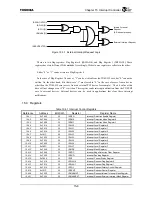
It is possible to make interrupt requests to external devices and interrupt requests (IRC interrupts) to
the TX49/H2 core by using a 32-bit interrupt request flag register. REQ[1]* signals are used as interrupt
output signals. Consequently, external interrupt requests can only be used when in the PCI External
Arbiter mode. Also, internal interrupt requests are assigned to interrupt number 13 of the Interrupt
Controller (IRC).
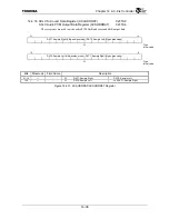
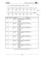
The following six registers set the interrupts.
•
Interrupt Request Flag Register (IRFLAG0, IRFLAG1)
•
Interrupt Request Polarity Control Register (IRPOL)
•
Interrupt Request Mask Register (IRMASKINT, IRMASKEXT)
•
Interrupt Request Control Register (IRRCNT)
The following formulas derive the interrupt generation conditions:
Internal interrupt request =
(|((IRFLAG[31:0] ^ IRPOL[31:0]) & IRMASKINT[31:0]))^ IRRCNT.INTPOL
External interrupt request =
(|((IRFLAG[31:0] ^ IRPOL[31:0] ) & IRMASKEXT[31:0]))^ IRRCNT.EXTPOL
In the above formulas, “^” indicates Exclusive OR operations and “|” indicates reduction operators
that perform an OR operation on all bits.
Also, the External Interrupt OD Control bit (IRRCNT.OD) of the Interrupt Request Control Register
can select whether the external interrupt supply signal is open drain output or totem pole output.
Summary of Contents for TMPR4925
Page 1: ...64 Bit TX System RISC TX49 Family TMPR4925 Rev 3 0 ...
Page 4: ......
Page 15: ...Handling Precautions ...
Page 16: ......
Page 18: ...1 Using Toshiba Semiconductors Safely 1 2 ...
Page 40: ...3 General Safety Precautions and Usage Considerations 3 18 ...
Page 42: ...4 Precautions and Usage Considerations 4 2 ...
Page 43: ...TMPR4925 ...
Page 44: ......
Page 54: ...Chapter 1 Features 1 8 ...
Page 58: ...Chapter 2 Block Diagram 2 4 ...
Page 88: ...Chapter 4 Address Mapping 4 12 ...
Page 226: ...Chapter 8 DMA Controller 8 58 ...
Page 260: ...Chapter 9 SDRAM Controller 9 34 ...
Page 480: ...Chapter 15 Interrupt Controller 15 32 ...
Page 554: ...Chapter 19 Real Time Clock RTC 19 8 ...
Page 555: ...Chapter 20 Removed 20 1 20 Removed ...
Page 556: ...Chapter 20 Removed 20 2 ...
Page 564: ...Chapter 21 Extended EJTAG Interface 21 8 ...
Page 580: ...Chapter 22 Electrical Characteristics 22 16 ...
Page 588: ...Chapter 24 Usage Notes 24 2 ...

