Chapter 10 PCI Controller
10-96
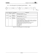
10.4.66 PDMAC Status Register (PDMSTATUS)
0xD214
31 29
28 24
23 20
19 16
Reserved FIFOCNT
FIFOWP FIFORP
R
R
R
:
Type
00000
0x0
0x0
:
Initial
value
15
14
13
12
11
10 9 8 7 6 5 4 3 2 1 0
Reserved
PCIACT ERRINT
DONEINT
CHNEN
XFRACT
ACCMP NCCMP NTCMP
Reserved
PCIPERR PCISERR
PCIERR
CHNERR
DATAERR
R R R R R R
R/W1C R/W1C
R/W1C R/W1C R/W1C
R/W1C
R/W1C :
Type
0 0 0 0 0 0 0 0 0 0 0 0 0
:
Initial
value
Bits Mnemonic Field
Name
Description
31:29
⎯
Reserved
⎯
28:24
FIFOCNT
FIFO Hold Count
FIFO Valid Entry Count (Initial value: 00000, R)
This field indicates the number of DWORDs written to the FIFO but not yet read. This
is a diagnostic function.
23:20 FIFOWP
FIFO Write
Pointer
FIFO Write Pointer (Initial value: 0x0, R)
This field indicates the next Write position in the FIFO. This is a diagnostic function.
19:16 FIFORP
FIFO Read
Pointer
FIFO Read Pointer (Initial value: 0x0, R)
This field indicates the next Read position in the FIFO. This is a dianostic function.
15
⎯
Reserved
⎯
14
PCIACT
PCI Active
PCI Active (Initial value: 0, R)
1: The PDMAC is requesting to transfer data to or from the PCI bus of it is currently
transferring data.
0: There is no active request or transfer from the PDMAC for the PCI bus.
13 ERRINT
Error Interrupt
Status
Error Interrupt Status (Initial value: 0, R)
Indicates whether to signal an error interrupt.
1: An error interrupt request exists.
0: No error interrupt request exists.
12 DONEINT
Normal Transfer
Complete
Interrupt Status
Normal Transfer Complete Interrupt Status (Initial value: 0, R)
Indicates whether a Normal Transfer Complete Interrupt is signaled.
This bit becomes “1” when either the Normal Chain Complete bit (NCCMP) is set and
the Normal Chain Complete Interrupt Enable bit (NCCMPIE) is set, or when the
Normal Data Transfer Complete bit (NTCMP) is set and the Normal Data Transfer
Complete Interrupt Enable bit (NTCMPIE) is set.
1: A Normal Transfer Complete Interrupt request exists.
0: No Normal Transfer Complete Interrupt request exists.
11
CHNEN
Chain Enable
Chain Enable (Initial value: 0, R)
This bit is a copy of the Chain Enable bit in the PDMAC Configuration Register.
10
XFRACT
Transfer Active
Transfer Active (Initial value: 0, R)
This bit is a copy of the Transfer Active bit in the PDMAC Configuration Register.
9 ACCMP
Abnormal Chain
Completion
Abnormal Chain Complete (Initial value: 0, R)
1: Indicates that the Chain transfer ended in an error state. In other words, this
reflects an OR operation of the PDMAC Status Register bits [4:0].
0: Indicates that no error has occurred in the Chain transfer since the previous error
bit was cleared.
Note: Bits [4:0] of the PDMAC Status Register must be cleared in order to clear this
bit.
8 NCCMP
Normal Chain
Completion
Normal Chain Complete (Initial value: 0, R/W1C)
1: Indicates that the Chain transfer ended in the Normal state.
0: Indicates that Chain transfer has not ended since this bit was previously cleared.
7 NTCMP
Normal Data
Transfer
Complete
Normal Data Transfer Complete (Initial value: 0, R/W1C)
1: Indicates that the data transfer specified by the PDMAC Register ended in the
Normal
state.
0: Indicates that data transfer has not ended since this bit was previously cleared.
Figure 10.4.66 PDMAC Status Register (1/2)
Summary of Contents for TMPR4925
Page 1: ...64 Bit TX System RISC TX49 Family TMPR4925 Rev 3 0 ...
Page 4: ......
Page 15: ...Handling Precautions ...
Page 16: ......
Page 18: ...1 Using Toshiba Semiconductors Safely 1 2 ...
Page 40: ...3 General Safety Precautions and Usage Considerations 3 18 ...
Page 42: ...4 Precautions and Usage Considerations 4 2 ...
Page 43: ...TMPR4925 ...
Page 44: ......
Page 54: ...Chapter 1 Features 1 8 ...
Page 58: ...Chapter 2 Block Diagram 2 4 ...
Page 88: ...Chapter 4 Address Mapping 4 12 ...
Page 226: ...Chapter 8 DMA Controller 8 58 ...
Page 260: ...Chapter 9 SDRAM Controller 9 34 ...
Page 480: ...Chapter 15 Interrupt Controller 15 32 ...
Page 554: ...Chapter 19 Real Time Clock RTC 19 8 ...
Page 555: ...Chapter 20 Removed 20 1 20 Removed ...
Page 556: ...Chapter 20 Removed 20 2 ...
Page 564: ...Chapter 21 Extended EJTAG Interface 21 8 ...
Page 580: ...Chapter 22 Electrical Characteristics 22 16 ...
Page 588: ...Chapter 24 Usage Notes 24 2 ...


