Chapter 10 PCI Controller
10-17
(5) DMA
Transfer
Initiation
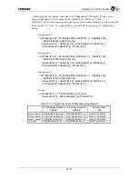
Setting the address of the DMA Command descriptor that is at the beginning of the Chain
List in the PDMAC Chain Address Register (PDMCA) automatically initiates DMA
transfer.
First, the values stored in each field of the DMA Command Descriptor that is at the beginning
of the Chain List are read to each corresponding PDMAC Register, then DMA transfer is
performed according to the read values.
If a value other than “0” is stored in the PDMAC Chain Address Register (PDMCA), data
transfer of the size stored in the PDMAC Count Register is complete, then the DMA
Command Descriptor value for the memory address specified by the PDMAC Chain Address
Register is read.
When the Chain Address field value reads a descriptor of “0”, the PDMAC Chain Address
Register value is not updated and the previous value (address of the Data Command
Descriptor at which the Chain Address field value is “0” when read) is held.
(6) Termination
Report
When DMA data transfer of all descriptor chains terminates normally, the Normal Chain
Complete bit (NCCMP) of the PDMAC Status Register is set. An interrupt is reported if the
Chain Termination Interrupt Enable bit (MCCMPIE) of the PDMAC Configuration register
(PDMCFG) is set.
Also, the Normal Data Transfer Complete bit (NTCMP) of the DPMAC Status Register is set
each time the DMA data transfer specified by a DMA Command Descriptor terminates
normally. An interrupt is reported if the Normal Data Transfer Complete Interrupt Enable bit
(NTCMPIE) of the PDMAC Configuration Register (PDMCFG) is set.
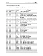
If an error is detected during DMA transfer, the error cause is recorded in the lower 5 bits of
the PDMAC Status Register and the transfer is aborted. An interrupt is then reported if the
Error Detection Interrupt Enable bit (ERRIE) of the PDMAC Configuration register is set.
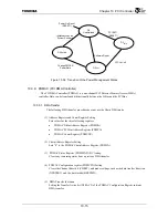
10.3.9.3 Dynamic Chain Operation
It is possible to dynamically add other DMA Command Descriptor Chains to a DMA Command
Descriptor Chain that is currently being processed when executing DMA data transfer. This is
done according to the following procedure.
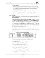
(1) DMA Command Descriptor Chain Construction
Constructs a DMA Command Descriptor Chain in memory.
(2) Addition of DMA Command Descriptor Chains
Substitutes the address of the command descriptor that is at the beginning of the descriptor
chain to be added into the Descriptor Chain Address field at the end of the DMA Command
Descriptor Chain that is currently performing DMA transfer.
Summary of Contents for TMPR4925
Page 1: ...64 Bit TX System RISC TX49 Family TMPR4925 Rev 3 0 ...
Page 4: ......
Page 15: ...Handling Precautions ...
Page 16: ......
Page 18: ...1 Using Toshiba Semiconductors Safely 1 2 ...
Page 40: ...3 General Safety Precautions and Usage Considerations 3 18 ...
Page 42: ...4 Precautions and Usage Considerations 4 2 ...
Page 43: ...TMPR4925 ...
Page 44: ......
Page 54: ...Chapter 1 Features 1 8 ...
Page 58: ...Chapter 2 Block Diagram 2 4 ...
Page 88: ...Chapter 4 Address Mapping 4 12 ...
Page 226: ...Chapter 8 DMA Controller 8 58 ...
Page 260: ...Chapter 9 SDRAM Controller 9 34 ...
Page 480: ...Chapter 15 Interrupt Controller 15 32 ...
Page 554: ...Chapter 19 Real Time Clock RTC 19 8 ...
Page 555: ...Chapter 20 Removed 20 1 20 Removed ...
Page 556: ...Chapter 20 Removed 20 2 ...
Page 564: ...Chapter 21 Extended EJTAG Interface 21 8 ...
Page 580: ...Chapter 22 Electrical Characteristics 22 16 ...
Page 588: ...Chapter 24 Usage Notes 24 2 ...

