141
CHAPTER 6 REAL-TIME OUTPUT FUNCTIONS
User’s Manual U12697EJ3V0UM
• Real-time output buffer registers (RTBL, RTBH)
These 4-bit registers save the output data beforehand. RTBL and RTBH are mapped to independent addresses
in the special function register (SFR) as shown in Figure 6-2.
When the 4 bits
×
2 channels operation mode is specified, RTBL and RTBH can be independently set with data.
In addition, if the addresses of both RTBL and RTBH are specified, the data in both registers can be read in
a batch.
When the 8 bits
×
1 channel operation mode is specified, writing 8-bit data to either RTBL or RTBH can set data
in either register. In addition, if the addresses of either RTBL and RTBH are specified, the data in both can be
read in a batch.
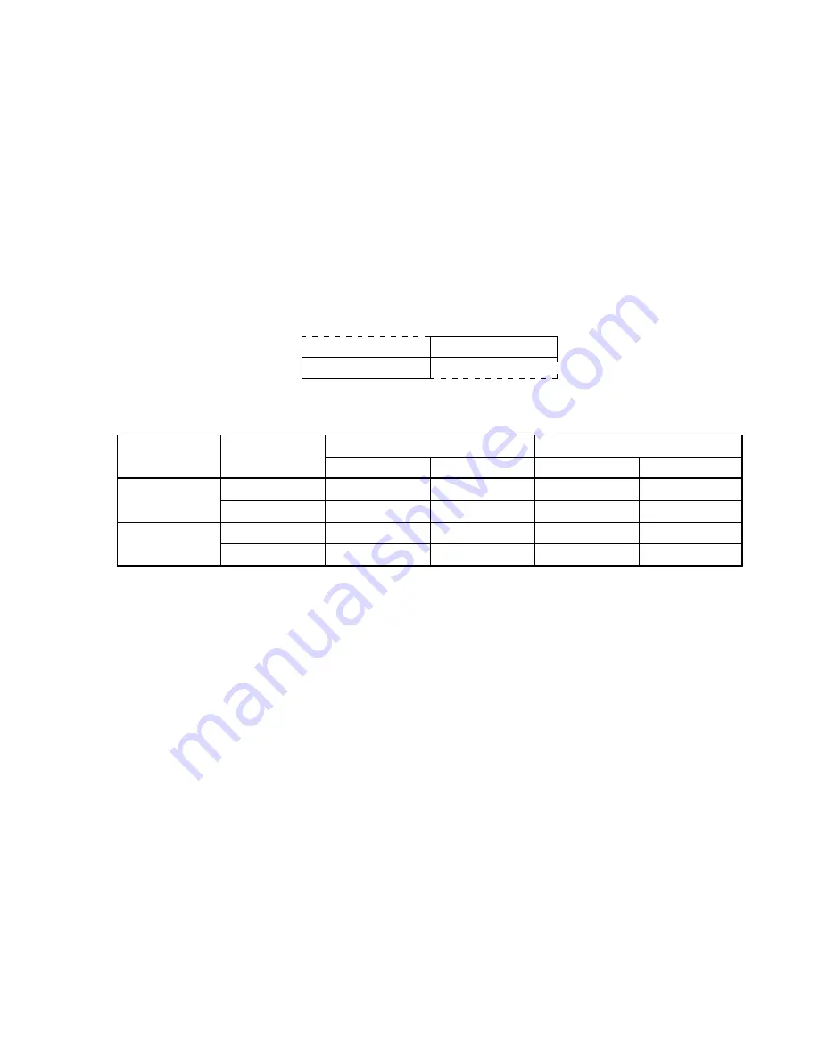
Table 6-2 lists the operations for manipulating RTBL and RTBH.
Figure 6-2. Configuration of Real-Time Output Buffer Register
Higher 4 bits
Lower 4 bits
0FF98H
RTBL
0FF99H
RTBH
Table 6-2. Operation for Manipulating Real-Time Output Buffer Registers
Operation Mode
Manipulated Register
Reading
Note 1
Writing
Note 2
Higher 4 Bits
Lower 4 Bits
Higher 4 Bits
Lower 4 Bits
4 bits
×
2 channels
RTBL
RTBH
RTBL
Invalid
RTBL
RTBH
RTBH
RTBL
RTBH
Invalid
8 bits
×
1 channel
RTBL
RTBH
RTBL
RTBH
RTBL
RTBH
RTBH
RTBL
RTBH
RTBL
Notes 1.
Only the bits specified in the real-time output port mode can be read. When the bits set in the port mode
are read, zeros are read.
2.
After setting the real-time output port, set the output data in RTBL and RTBH until the real-time output
trigger is generated.


