181
CHAPTER 8 16-BIT TIMER/EVENT COUNTER
User’s Manual U12697EJ3V0UM
(4) Data hold timing of capture register
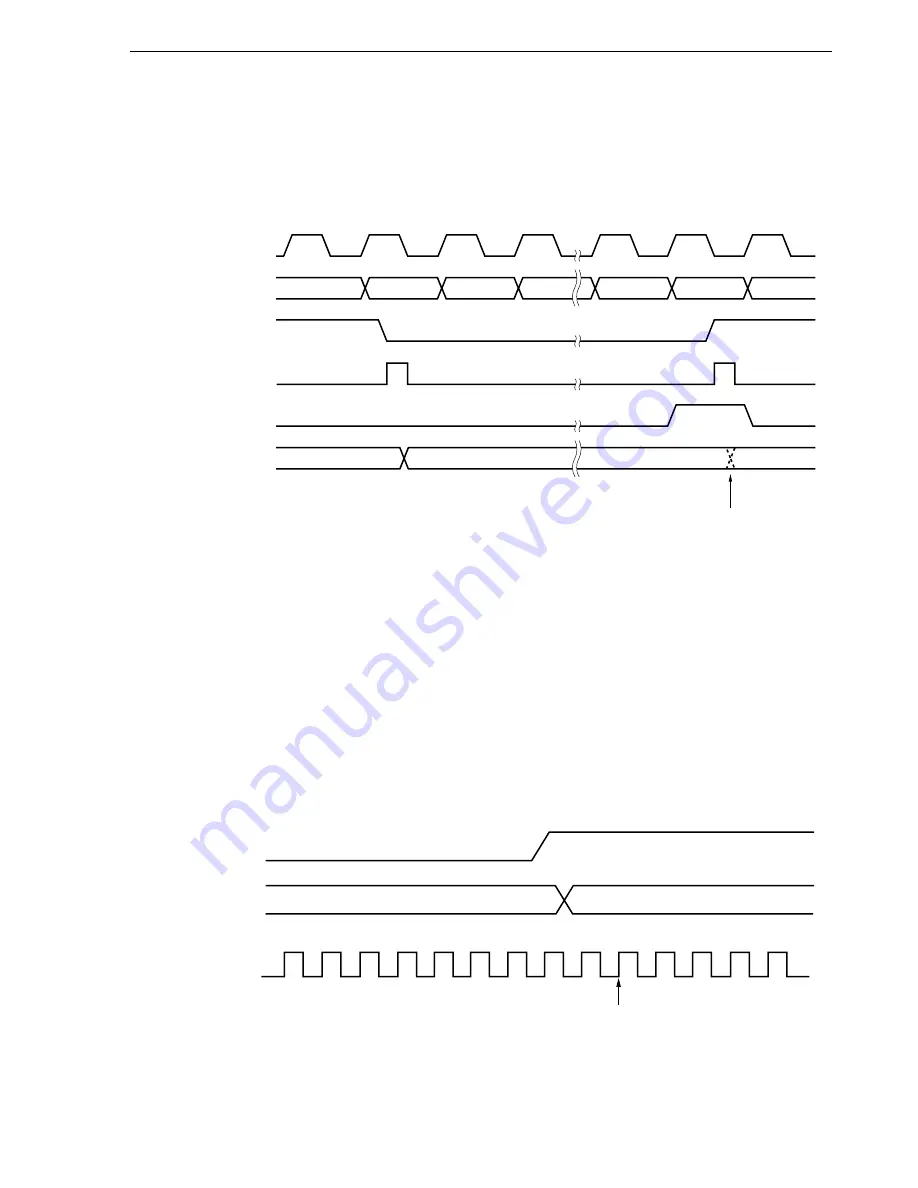
If the valid edge is input to the TI00/P35 pin while 16-bit capture/compare register 01 (CR01) is read, CR01
performs the capture operation, but this capture value is not guaranteed. However, the interrupt request flag
(INTTM01) is set as a result of detection of the valid edge
Figure 8-31. Data Hold Timing of Capture Register
TM0 count value
N
N + 1
N + 2
M
M + 1
M + 2
N + 1
X
Count pulse
Edge input
Interrupt request flag
Capture read signal
Value loaded to CR01
Capture operation
ignored
(5) Setting valid edge
The valid edge of the TI00/P35 pin sets 0,0 in bits 2 and 3 of 16-bit timer mode control register 0 (TMC0), and
this setting should be made the moment timer operations have been halted. The valid edge is set with bits 4
and 5 of prescaler mode register 0 (ES00, ES01).
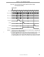
(6) Cautions on edge detection
<1>
When the TI00/TI01 pin is high level immediately after system reset, it may be detected as a rising edge
after the first 16-bit timer/event counter operation is enabled. Bear this in mind when pulling up, etc.
<2>
Regardless of whether interrupt acknowledgement is disabled (DI) or enabled (EI), the edge of the external
input signal is detected at the second clock after the signal is changed.
Edge detection
TI00/TI01 pin input
Count clock
Interrupt acknow-
ledgement status
Interrupt disabled (DI)
Interrupt enabled (EI)


