143
CHAPTER 6 REAL-TIME OUTPUT FUNCTIONS
User’s Manual U12697EJ3V0UM
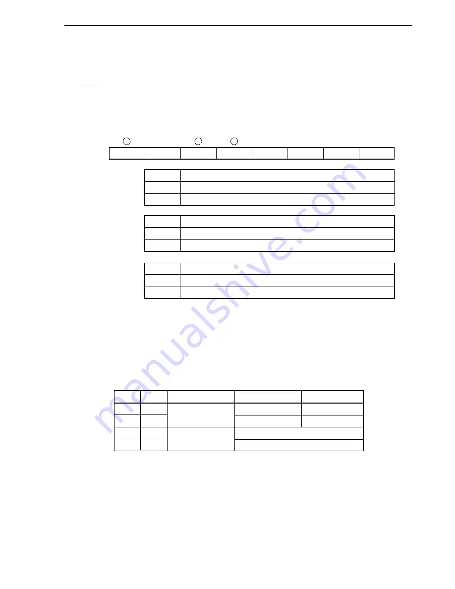
(2) Real-time output port control register (RTPC)
This register sets the operation mode and output trigger of the real-time output port.
Table 6-3 shows the relationships between the operation modes and output triggers of the real-time output port.
RTPC is set by a 1-bit or 8-bit memory manipulation instruction.
RESET input sets RTPC to 00H.
Figure 6-4. Format of Real-Time Output Port Control Register (RTPC)
Address: 0FF9BH After reset: 00H R/W
Symbol
7
6
5
4
3
2
1
0
RTPC
RTPOE
0
BYTE
EXTR
0
0
0
0
RTPOE
Real-time output port operation control
0
Operation disabled
1
Operation enabled
Note
BYTE
Real-time output port operation mode
0
4 bits
×
2 channels
1
8 bits
×
1 channel
EXTR
Real-time output control by INTP2
0
Do not set INTP2 as real-time output trigger
1
Set INTP2 as real-time output trigger
Note
When real-time output operation is enabled (RTPOE = 1), the values of the real-time output buffer registers
(RTBH and RTBL) are transferred to the real-time output port output latch.
Caution When INTP2 is specified as an output trigger, specify the valid edge using external interrupt rising
edge enable register 0 (EGP0) and external interrupt falling edge enable register 0 (EGN0).
Table 6-3. Operation Modes and Output Triggers of Real-Time Output Port
BYTE
EXTR
Operation Mode
RTBH
→
Port Output RTBL
→
Port Output
0
0
4 bits
×
2 channels
INTTM2
INTTM1
0
1
INTTM1
INTP2
1
0
8 bits
×
1 channel
INTTM1
1
1
INTP2


