Ethernet communication
7.6 HT 8
Manual
218
Commissioning Manual, 05/2008, 6FC5397–4CP10–4BA0
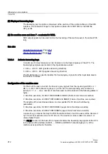
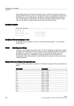
The user softkeys are inscribed as U1 to U16 by default:
HT8_xx.INI (excerpt)
[CPFSoftkey Text]
U1 = "U1"
; max. 2*10 characters,
U2 = "U2"
; Line break occurs via %n
U3 = "U3"
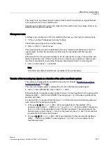
To inscribe a user softkey, the existing character string "Ux" must be replaced by the desired
character string, e.g. "Door open" A maximum of 2 lines are available for inscription of a
traversing key. It is recommended, the specification in the file notwithstanding, that only a
max. of 8 characters be used per line. For a two-line inscription, the two character strings
must be separated by %n (line break), e.g. "Cooling%nOff".
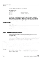
Inscription examples:
HT8_xx.INI (excerpt)
[CPFSoftkey Text]
U1 = "CANCEL"
; One-line display
U2 = "Cooling%nOff"
; Two-line display
U3 = "Door open"
; One-line display
7.6.5.8
MCS/WCS coordinate system switchover
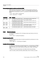
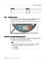
The switching of the coordinate system on HT 8 takes place via the vertical "MCS/WCS"
softkey in the CPF menu (activation via "U" key). The following input signal is set on
actuating the softkey:
●
EB n + 0, Bit 0 = 1 (MCS/WCS)
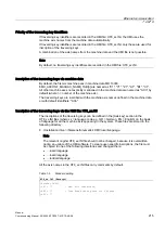
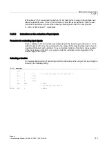
The transfer of the input signal to the HMI input signal (DB 19, DBX 0.7) must be undertaken
by the user (machine manufacturer) via an edge detection in the cyclic part of the PLC user
program (OB 1). The following listing shows an implementation option:
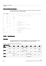
OB 1 (excerpt)
U
E
0.0
// Evaluation of positive edge from EB n+0, Bit0
FBD
G
200.1
// Store result in Marker 200.1
U
G
200.1
// Load result
X
DB19.DBX
0.7
// XOR of the result with HMI input signal
=
DB19.DBX
0.7
// Write HMI signal
Note
The input data area from E0 and the use of Marker M200.1 are mere assumptions for illustration
purposes.
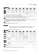
Result: The HMI signal (DB 19, DBX 0.7) changes its state with each positive edge of the
input signal (EB n + 0, Bit 0).

