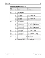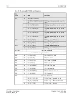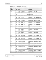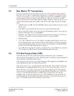
4. DMA
122
PowerSpan II User Manual
80A1010_MA001_09
Integrated Device Technology
www.idt.com
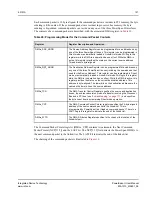
Figure 18: DMA Command Packet Linked-List
4.4.1
Initializing a Linked-List Mode Transfer
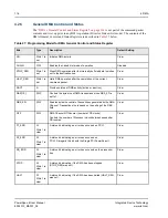
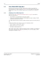
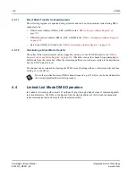
A Linked-List mode DMA transfer is configured using the following steps:
1.
Set-up the command packet linked-list in memory accessible to any one of the PowerSpan II’s
three ports. The command packet port selection is independent of the port selected as the source or
destination port.
2.
Configure DMAx_ATTR parameters and DMAx_GCSR.
3.
Set-up the NCP[31:5] field to point to the first command packet.
4.
Ensure the BC[23:0] field in the DMA Transfer Control Register is 0.
5.
Clear all status bits in the DMA General Control and Status Register.
6.
Set the GO bit.
The steps to configure a Linked-List mode DMA transfer are illustrated in
Reserved
DMAx_SRC_ADDR
Reserved
DMAx_DST_ADDR
Reserved
DMAx_TCR
Reserved
DMAx_CPP
Reserved
DMAx_SRC_ADDR
Reserved
DMAx_DST_ADDR
Reserved
DMAx_TCR
Reserved
DMAx_CPP
First Command Packet
Second Command Packet
0x00
0x04
0x08
0x0C
0x10
0x14
0x18
0x1C
Address
Offset:


