4. DMA
116
PowerSpan II User Manual
80A1010_MA001_09
Integrated Device Technology
www.idt.com
4.2.5
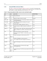
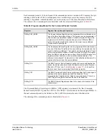
General DMA Control and Status
“DMA x General Control and Status Register” on page 314
is not part of the command packet
contents and is set up prior to any DMA operation (Direct or Linked-List mode). The contents of the
DMA General Control and Status Register are described in
below.
Table 27: Programming Model for DMA General Control and Status Register
Bits
Type
Description
Default Setting
GO
Write 1 to
set
Initiates DMA activity
Clear
CHAIN
R/W
Enables the Linked-List mode of operation.
Disabled
STOP_REQ
Write 1 to
set
Stops DMA operation after the internally buffered data is written
out to the destination bus.
Clear
HALT_REQ
Write 1 to
set
Halts DMA operation after the completion of the current
command packet.
Clear
DACT
R
Provides status of DMA activity (active or inactive).
Clear
DBS[1:0]
R/W
Controls the byte size of DMA transactions when DBS_EN is
set to 1.
Clear
DBS_EN
R/W
Enables byte size control of transactions generated by the DMA
Channel. Transaction size is based on the setting of the DBS
field.
Clear
OFF
R/W
DMA Channel Off Counter (number of PB clocks)
Controls the number of Processor clocks between sequential
PB tenures.
Clear
P1_ERR
R/
Write 1 to
clear
A status bit indicating an error has occurred on PCI-1.
Clear
P2_ERR
R/
Write 1 to
clear
A status bit indicating an error has occurred on
PCI-2. Disregard this bit with the Single PCI PowerSpan II.
Clear
PB_ERR
R/
Write 1 to
clear
A status bit indicating an error has occurred on the processor
bus.
Clear
STOP
R/
Write 1 to
clear
A status bit indicating if the DMA has been stopped
(STOP_REQ was set)
Clear
HALT
R/
Write 1 to
clear
A status bit indicating if the DMA has been halted (HALT_REQ
was set).
Clear

