5. I2C/EEPROM
134
PowerSpan II User Manual
80A1010_MA001_09
Integrated Device Technology
www.idt.com
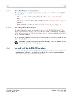
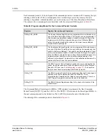
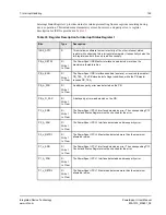
When the reset sequence is initiated by assertion of PB_RST_, P1_RST# or P2_RST#, the first byte of
the EEPROM is read to determine the loading sequence desired. All bytes for the selected load option
are read from the EEPROM, but only a subset of PowerSpan II registers are updated. This subset is
defined by the external reset pin that initiated the reset sequence. Only those register bits affected by
the active reset pin(s) are updated with EEPROM contents. See
“Register Descriptions” on page 235
for more information.
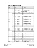
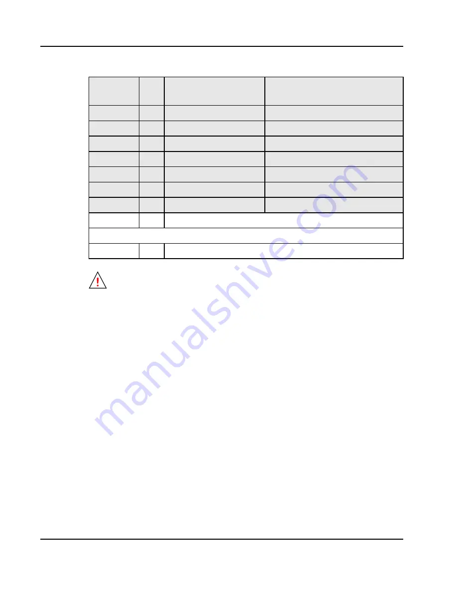
0x35
7-0
P2_ID[DID[7:0]]
PCI-2 Device ID bits 7-0
0x36
7-0
P2_ID[VID[15:8]]
PCI-2 Vendor ID bits 15-8
0x37
7-0
P2_ID[VID[7:0]]
PCI-2 Vendor ID bits 7-0
0x38
7-0
P2_CLASS[BASE]
PCI-2 Base Class Code
0x39
7-0
P2_CLASS[SUB]
PCI-2 Sub Class Code
0x3A
7-0
P2_CLASS[PROG]
PCI-2 Programming Interface
0x3B
7-0
P2_CLASS[RID]
PCI-2 Revision ID
0x3C-0x3F
7-0
PowerSpan II Reserved
End of load sequence
0x40-0xFF
7-0
Reserved for PCI Vital Product Data (VPD)
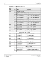
When a long EEPROM load is executed, the PB Slave Image 0 is enabled automatically. The
IMG_EN bit is set to 1 in the PB_S1_CTL register.
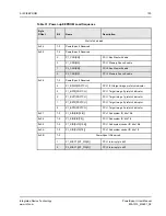
Table 31: Power-up EEPROM Load Sequence
Byte
Offset
Bit
Name
Description

