12. Register Descriptions
337
PowerSpan II User Manual
80A1010_MA001_09
Integrated Device Technology
www.idt.com
12.5.49
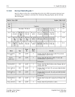
Interrupt Map Register Mail Box
Each map field assigns an interrupt output pin to the corresponding interrupt source.
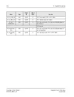
describes the mapping of interrupt sources to the external interrupt pins. The shaded entries
indicate unsupported combinations for the Single PCI PowerSpan II.
Register Name: IMR_MBOX
Register Offset: 0x420
PCI
Bits
Function
PB
Bits
31-24
MBOX7_MAP
0
MBOX6_MAP
0
0-7
23-16
MBOX5_MAP
0
MBOX4_MAP
0
8-15
15-08
MBOX3_MAP
0
MBOX2_MAP
0
16-23
07-00
MBOX1_MAP
0
MBOX0_MAP
0
24-31
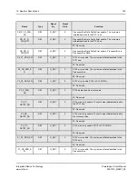
Name
Type
Reset
By
Reset
State
Function
MBOX7_MAP[2:0]
R/W
G_RST
0
Map Mailbox #7 to an interrupt pin.
MBOX6_MAP[2:0]
R/W
G_RST
0
Map Mailbox #6 to an interrupt pin.
MBOX5_MAP[2:0]
R/W
G_RST
0
Map Mailbox #5 to an interrupt pin.
MBOX4_MAP[2:0]
R/W
G_RST
0
Map Mailbox #4 to an interrupt pin.
MBOX3_MAP[2:0]
R/W
G_RST
0
Map Mailbox #3 to an interrupt pin.
MBOX2_MAP[2:0]
R/W
G_RST
0
Map Mailbox #2 to an interrupt pin.
MBOX1_MAP[2:0]
R/W
G_RST
0
Map Mailbox #1 to an interrupt pin.
MBOX0_MAP[2:0]
R/W
G_RST
0
Map Mailbox #0 to an interrupt pin.
Table 81: Mapping Definition
Map Field
Interrupt Pin
000
P1_INTA#
001
P2_INTA#
010
INT[0]_
011
INT[1]_
100
INT[2]_


