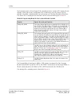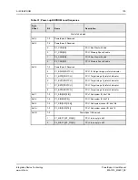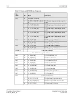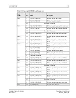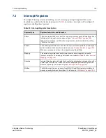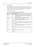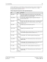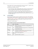
5. I2C/EEPROM
135
PowerSpan II User Manual
80A1010_MA001_09
Integrated Device Technology
www.idt.com
5.3
Bus Master I
2
C Transactions
I
2
C master reads and writes can be performed from any one of the PowerSpan II’s three interfaces
—
PB, PCI-1 or PCI-2. These I
2
C transactions are generated by accessing the
Control and Status Register” on page 322
. This register can be used to access EEPROMs or perform
arbitrary single byte transfers to other I
2
C
compatible devices. Since the I
2
C Interface is a shared
resource, software must use a PowerSpan II register semaphore, SEMAx, to acquire exclusive access to
interface before initiating transactions with I2C_CSR. The I2C_CSR register contains the following
fields:
•
EEPROM Address (ADDR): The 8-bit EEPROM address specifies the address for byte writes and
random reads.
•
Data (DATA): The 8-bit data field is the source for writes and destination for reads.
•
Device Code (DEV_CODE): Device code is the 4-bit field that specifies the I
2
C device type. The
default is 1010b which is the code for EEPROMs.
•
Chip Select (CS): Chip select is the 3-bit field use to select one of the eight slaves on the I
2
C bus.
The device code and chip select fields together form the I
2
C 7-bit device address.
•
Read/Write (RW)
•
Active (ACT): When the active bit is set, a transfer is in progress and the register is in read-only
mode. After performing a write or read access, the user must poll the active bit until it is negated
before performing other transfers. The active bit is also asserted during power-up EEPROM load
and when a PCI Vital Product Data transfer is in progress.
•
Error (ERR): If the PowerSpan II is unable to complete an I
2
C access, the ERR bit is set when the
ACT is negated. The ERR bit must be cleared before attempting another access.
5.4
PCI Vital Product Data (VPD)
Vital Product Data (VPD) is the information that uniquely defines items such as the hardware,
software, and microcode elements of a system. VPD also provides a mechanism for storing information
such as performance and failure data on a device.
VPD resides in a local storage device. PowerSpan II supports VPD through the serial EEPROM. If an
external EEPROM is not used, the VPD feature is disabled.
There are four bits in
associated with PCI Vital Product Data: VPD_EN and VPD_CS[2:0].
These bits may also be programmed in the
“Miscellaneous Control and Status Register” on page 318
.
When VPD_EN is set, PowerSpan II supports PCI Vital Product Data through the VPD capabilities
registers in the PCI Configuration Space of the designated Primary PCI Interface (see
). The VPD may be located in two different places: the upper 192 bytes of the first
EEPROM (VPD_CS=000) or the entire 256 bytes of a second EEPROM with chip select VPD_CS.
The VPD Enable and VPD Chip Select fields in the
“Miscellaneous Control and Status Register” on
are initialized as part of the short load post reset sequence.

